Image processing apparatus and method thereof
a technology of image processing and encoding apparatus, which is applied in the direction of signal generators with optical-mechanical scanning, color television with bandwidth reduction, signal generation, etc., can solve the problems of increasing circuit size and power consumption, increasing processing time, etc., and achieve accurate determination of cu sizes
- Summary
- Abstract
- Description
- Claims
- Application Information
AI Technical Summary
Benefits of technology
Problems solved by technology
Method used
Image
Examples
first exemplary embodiment
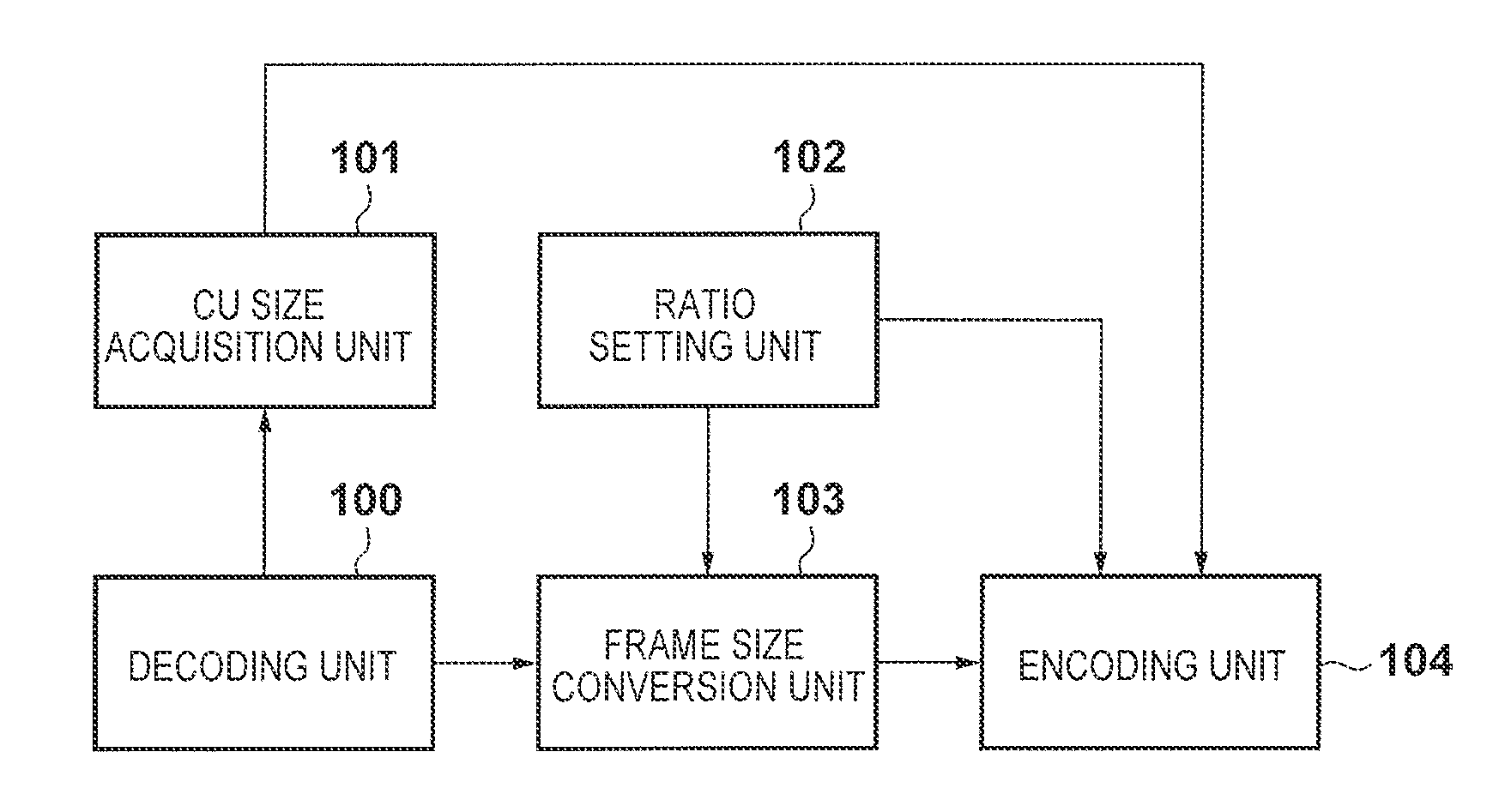
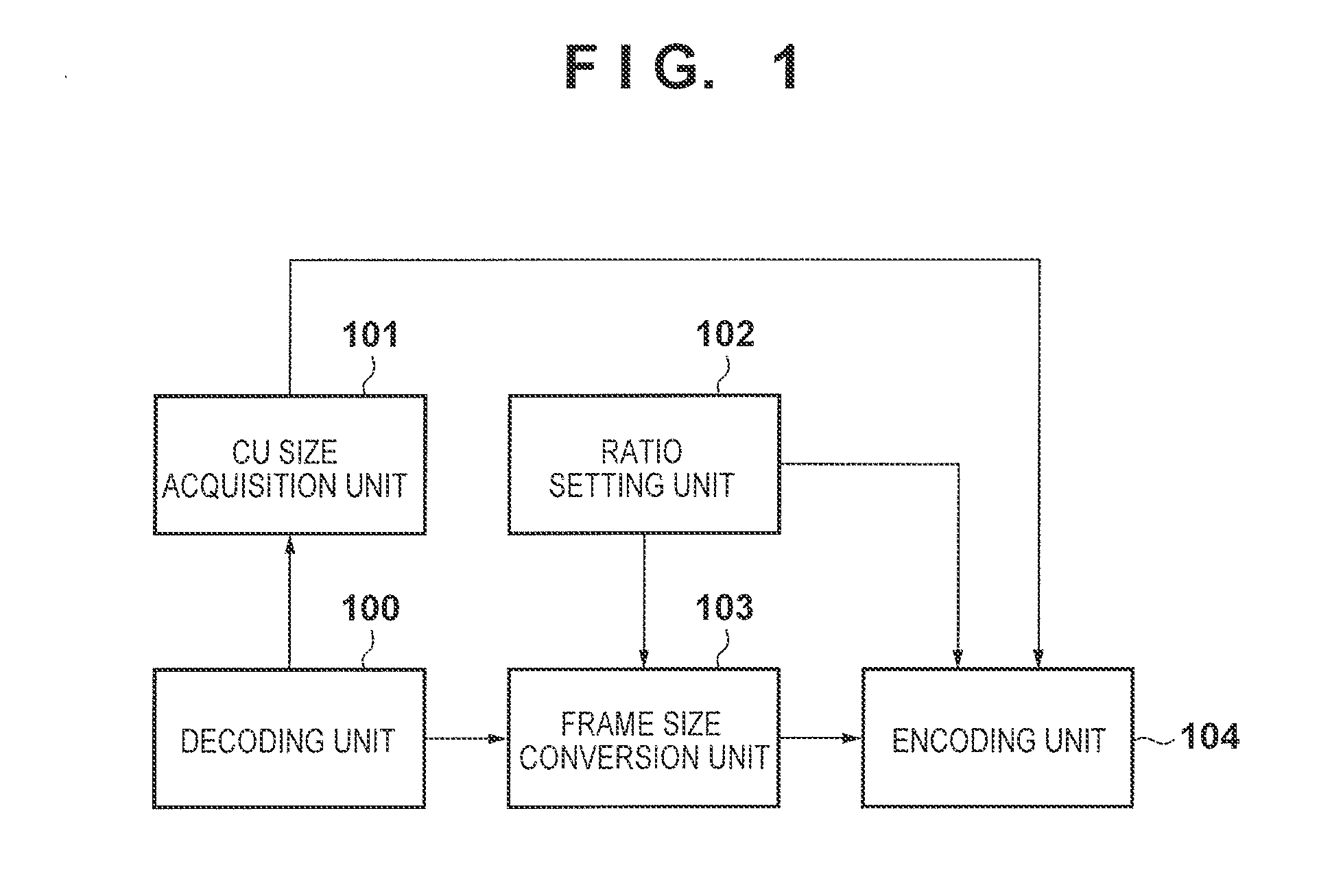
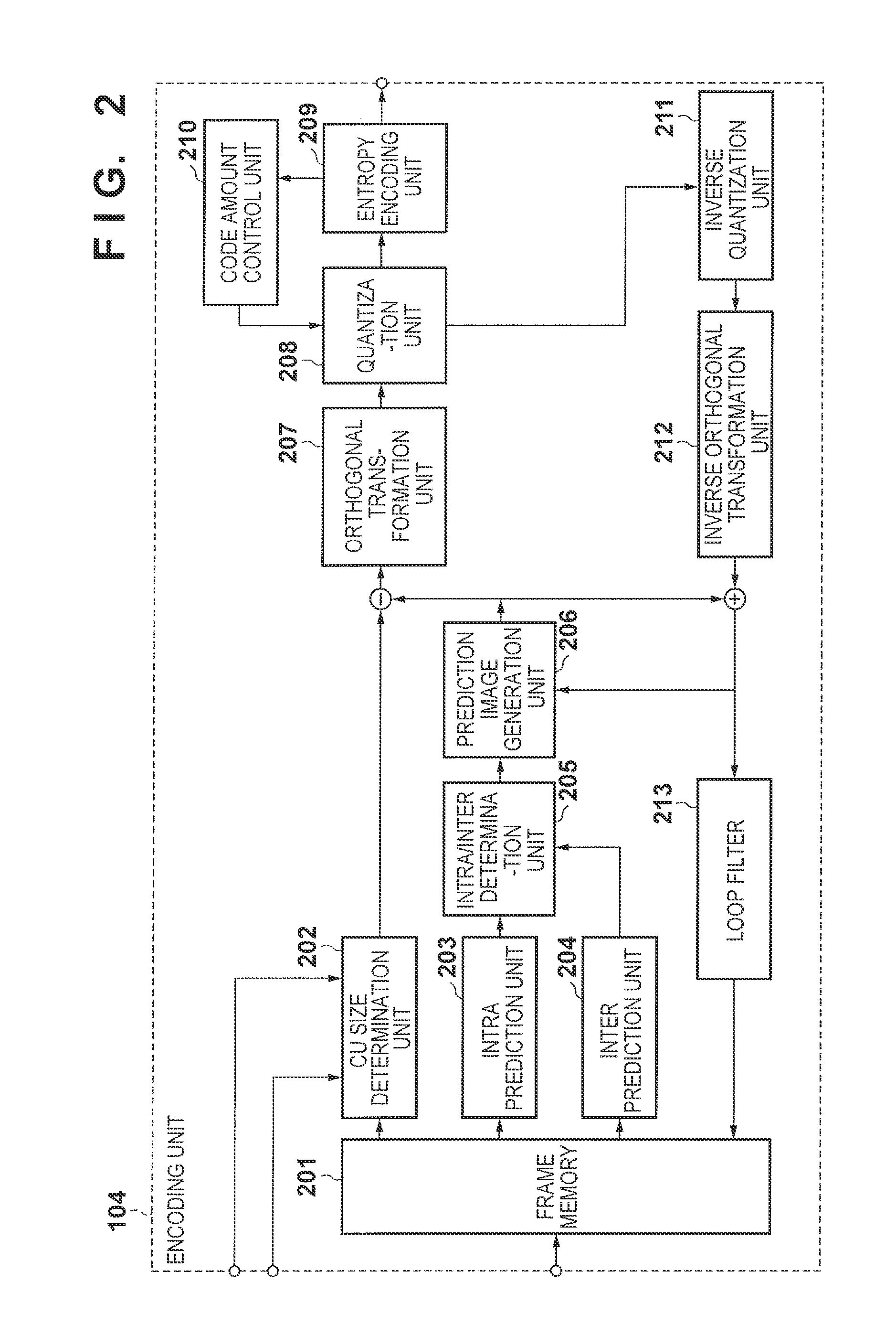
[0023]The first exemplary embodiment will be described below with reference to the accompanying drawings. FIG. 1 is a block diagram for illustrating components of an image processing apparatus (or encoding apparatus) to which the first and second exemplary embodiments are applied. FIG. 2 is a block diagram for illustrating components of an encoding unit according to the first exemplary embodiment. This image processing apparatus can be an arbitrary information processing terminal such as a personal computer, digital camera, cell phone, smartphone, PDA, tablet terminal, or TV set.
[0024]This image processing apparatus includes a decoding unit 100, a CU size acquisition unit 101, a ratio setting unit 102, a frame size conversion unit 103, and an encoding unit 104. At least of the decoding unit 100, the CU size acquisition unit 101, the ratio setting unit 102, the frame size conversion unit 103, and the encoding unit 104 may have a hardware structure. These units may be implemented in t...
second exemplary embodiment
[0049]The first exemplary embodiment has exemplified the method of determining CU sizes in a re-encoded moving image based on the CU size distribution of a decoded moving image and the ratio between the frame size of the decoded moving image and that of an image at the time of re-encoding. In contrast to this, in the second exemplary embodiment, if a pixel size of 8×8 pixels is selected as a CU size in a decoded moving image, an orthogonal transformation size is set to a block size smaller than a size of 8×8 pixels in a corresponding image region to be re-encoded. This operation is executed as a further different operation. This makes it possible to reflect, in an operation at the time of re-encoding, the distribution of image data having a fine structure, that is, many high frequency components, in a decoded moving image. It is therefore possible to maintain high image quality.
[0050]In this case, pixel sizes subjected to orthogonal transformation are those based on a scheme capable...
application example
[0056]An example of applying the above operation procedure will be described subsequently with reference to FIGS. 8A to 8C. FIG. 8A shows the CU size distribution of a decoded moving image. FIG. 8B shows a CU size distribution if a decoded moving image is re-encoded upon being resized at a frame size ratio of 2:1. FIG. 8C shows a TU size in the re-encoded moving image. In the second exemplary embodiment, CU sizes at the time of re-encoding are also determined in accordance with a frame size ratio as in the first exemplary embodiment. On that basis, if a CU size in a decoded moving image is the minimum size of 8×8 pixels which can be selected in terms of specifications, an orthogonal transformation process is performed for the corresponding CU in the encoded moving image while a pixel size of 4×4 pixels is set as a TU size.
[0057]An image block region using a CU size of 8×8 pixels in the decoded moving image in FIG. 8A can be determined to basically have a complex structure as a picto...
PUM
 Abstract
Description
Claims
Application Information
 - R&D
- Intellectual Property
- Life Sciences
- Materials
- Tech Scout
- Unparalleled Data Quality
- Higher Quality Content
- 60% Fewer Hallucinations
Browse by: Latest US Patents, China's latest patents, Technical Efficacy Thesaurus, Application Domain, Technology Topic, Popular Technical Reports.
© 2025 PatSnap. All rights reserved.Legal|Privacy policy|Modern Slavery Act Transparency Statement|Sitemap|About US| Contact US: help@patsnap.com


