Method and arrangement for checking the tightness of a vessel

a tightness and vessel technology, applied in the direction of fluid tightness measurement, combustion air/fuel air treatment, instruments, etc., can solve the problems of limited tightness check accuracy, underpressure or overpressure reduction,

Inactive Publication Date: 2005-01-11
ROBERT BOSCH GMBH
View PDF6 Cites 2 Cited by
  • Summary
  • Abstract
  • Description
  • Claims
  • Application Information

AI Technical Summary

Benefits of technology

Advantageously, the pressure source is an electromagnetically driven pump. The

Problems solved by technology

When charging the vessel filled with the fluid with an underpressure or overpressure, the outgassing or condensation of the fluid disposed in the vessel and/or th

Method used


Image

  • Method and arrangement for checking the tightness of a vessel
  • Method and arrangement for checking the tightness of a vessel
  • Method and arrangement for checking the tightness of a vessel

Examples


Embodiment Construction

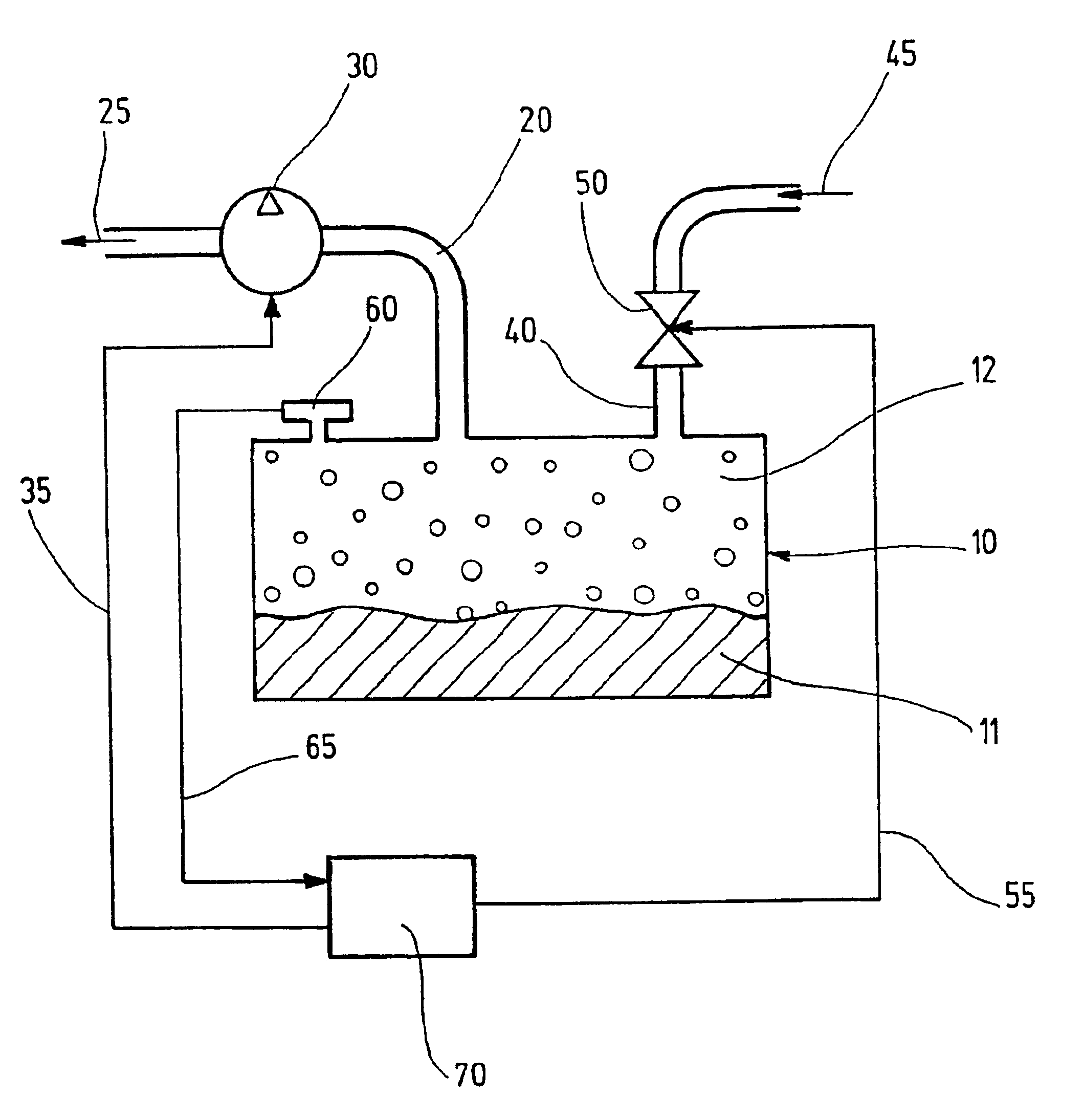
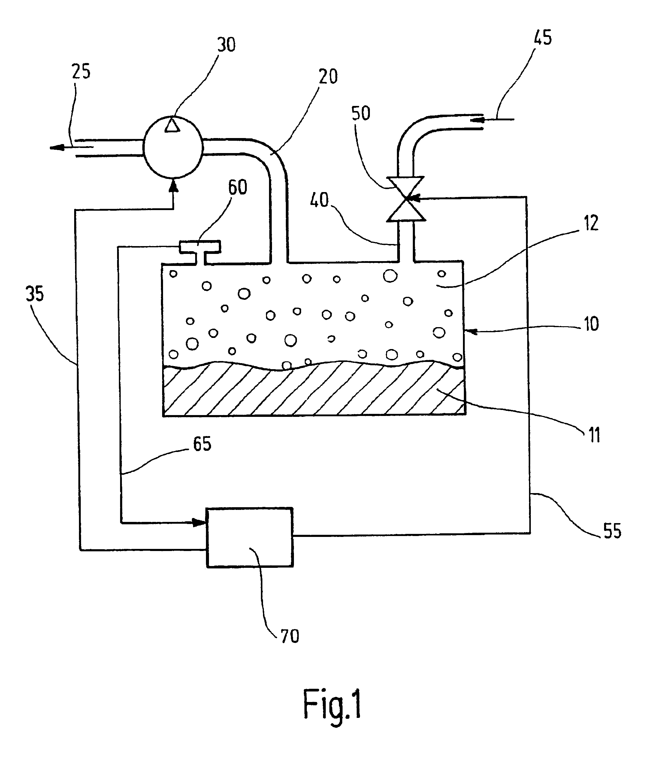
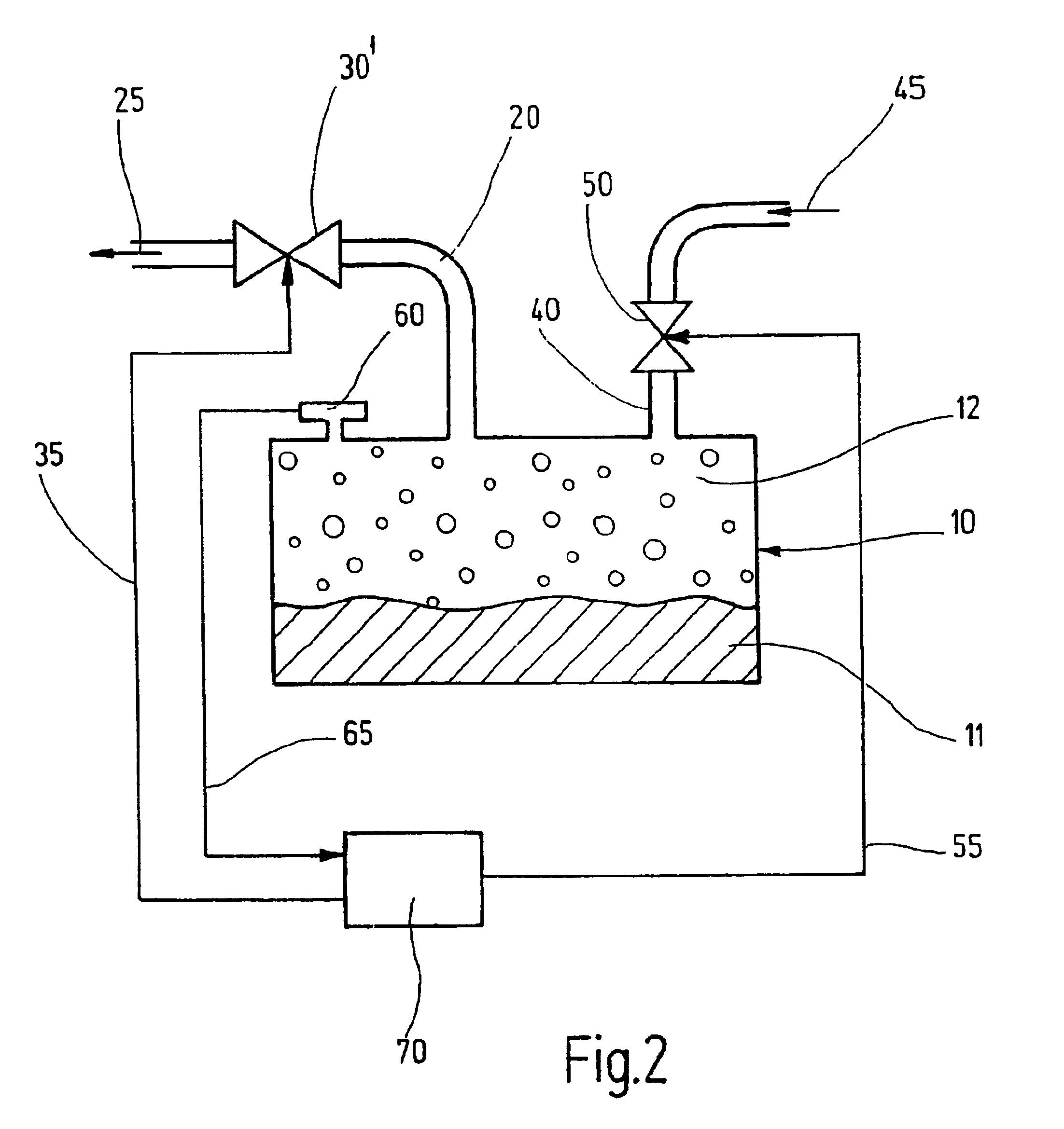
The method of the invention is described hereinafter with respect to the tank systems shown in FIGS. 1 and 2. The tank system has a tank 10 in a motor vehicle having an internal combustion engine. The method is not limited to a tank 10 of a motor vehicle; rather, the invention can be applied for a tightness check in any desired vessel or tank system for various fluids, especially fuels and especially tank-venting systems of tank systems in different areas, for example, in vessels utilized in the chemical industry.

The tank 10 shown schematically in FIG. 1 is to be checked with respect to tightness. The tank 10 includes a fresh-air supply channel 40 wherein a controllable check valve 50 is mounted. Fresh air can flow to the tank 10 in the direction of arrow 45 through this fresh-air supply channel 40. Furthermore, the tank 10 includes a discharge channel 20 wherein an electromagnetically driven underpressure pump 30 is mounted. In lieu of the pump 30, a mechanically and / or hydraulical...


PUM


Abstract

In order to reduce the influence of the elasticity of components of a vessel (10, 20, 30, 40, 50) and/or of an outgassing of a liquid fluid (11), which is disposed in the vessel (10, 20, 30, 40, 50) or a condensation of a gas disposed in the vessel or of a gas mixture (12) on an underpressure or an overpressure in the vessel, a gas mass flow is controlled to obtain a constant underpressure or overpressure in the vessel. In this way, a leak of the vessel can be detected with great reliability and the size of the leak can be computed with great accuracy. The vessel is especially a vessel of a tank system and tank-venting system of a motor vehicle having an internal combustion engine. In the event that a gas mass flow adjusts, which is constant in average, and which is greater than a pregivable limit value, a conclusion is drawn as to the presence of a leak. The size of the leak is computed from a signal characterizing the constant gas mass flow.

Description

BACKGROUND OF THE INVENTIONTo check the tightness of a fluid-filled vessel, the vessel is charged with an underpressure or an overpressure. The vessel can, for example, be part of a tank system of a motor vehicle having an internal combustion engine. In the event that a leakage is present, fluid flows through the locations of non-tightness to the vessel or out of the vessel whereby the underpressure or overpressure is reduced. This underpressure reduction or overpressure reduction functions as an index for the size of the leak.For example, in the tank system of a motor vehicle having an internal combustion engine, a mixture, especially of fuel vapor and air, is drawn from the tank-venting system by suction because of an underpressure in an intake manifold of the engine. For this purpose, a tank-venting valve is opened between the intake manifold and the tank system. To prevent fresh air from flowing after into the tank system, a fresh air feed line of the tank system is closed by a ...

Claims


Application Information

Patent Timeline
IPC IPC(8): F02M25/08F02M37/10F02M37/08G01M3/32G01M3/26G01M3/02
CPCF02M25/0809F02M25/0818G01M3/3254F02M37/106F02M25/089F02M2025/0881G01M3/02
Inventor LEDERER, DIETERLEDERLE, KARL-BERNHARDSIRUR, SUJAY
Owner ROBERT BOSCH GMBH
Why Eureka
Try Eureka