Buffing ball made of foam material

Active Publication Date: 2005-06-09
LAKE COUNTRY MFG
View PDF12 Cites 13 Cited by
  • Summary
  • Abstract
  • Description
  • Claims
  • Application Information

AI Technical Summary

Benefits of technology

[0008] In an alternate embodiment, the spiral slit may be replaced by a series of slits in multiple axially spaced planes that extend generally perpendicular to the rotational axis. Both the perpendicularly extending slits and the radially extending slits extend into the foam body less than the distance to the rotational axis. Preferably, the radially ex

Problems solved by technology

Because the prior art buffing ball is made of individual thin layers of cloth that are only slightly compressible and are stacked and clamped axially along the center axis, there is a tendency for relative rubbing movement between the layers which can result in fretting and wearing of the cloth.
Also, because the individual layers are inherently thin, there is also a tendency for the fingers to tear more easily from the body of the cloth layer.

Method used


Image

  • Buffing ball made of foam material
  • Buffing ball made of foam material
  • Buffing ball made of foam material

Examples


Embodiment Construction

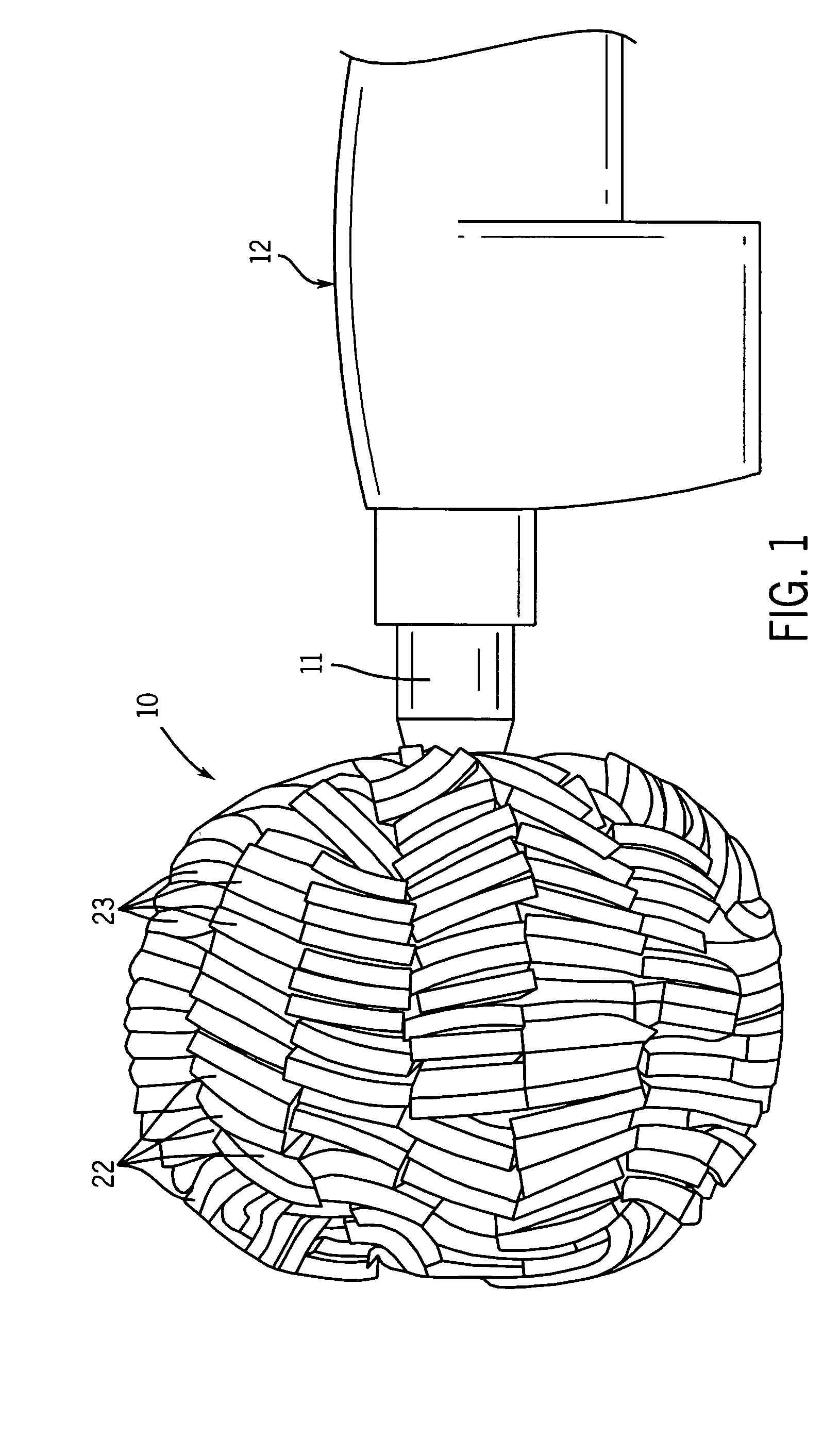
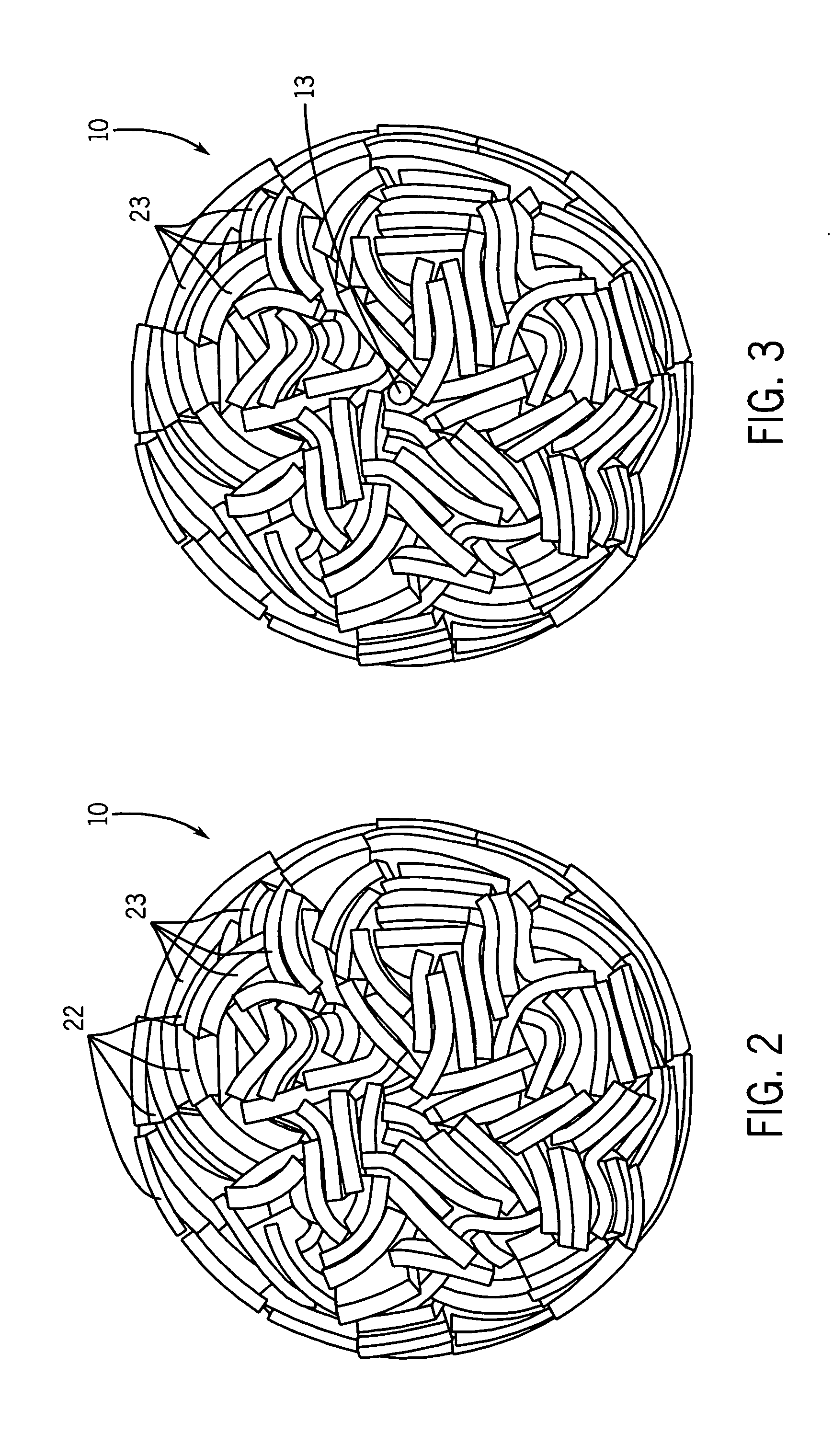
[0022]FIGS. 1-3 show a foam buffing and polishing ball 10 of the present invention. In FIG. 1, the ball is mounted on the chuck 11 of a driving tool 12 to rotate the ball about its rotational axis. In FIG. 3, the mounting end of the ball 10 is shown where a central drive shaft 13 is connected to the chuck 11 of the driving tool. The remainder of the compressing and fastening system used to shape the buffing and polishing ball 10 is contained within the interior of the ball and not normally visible.

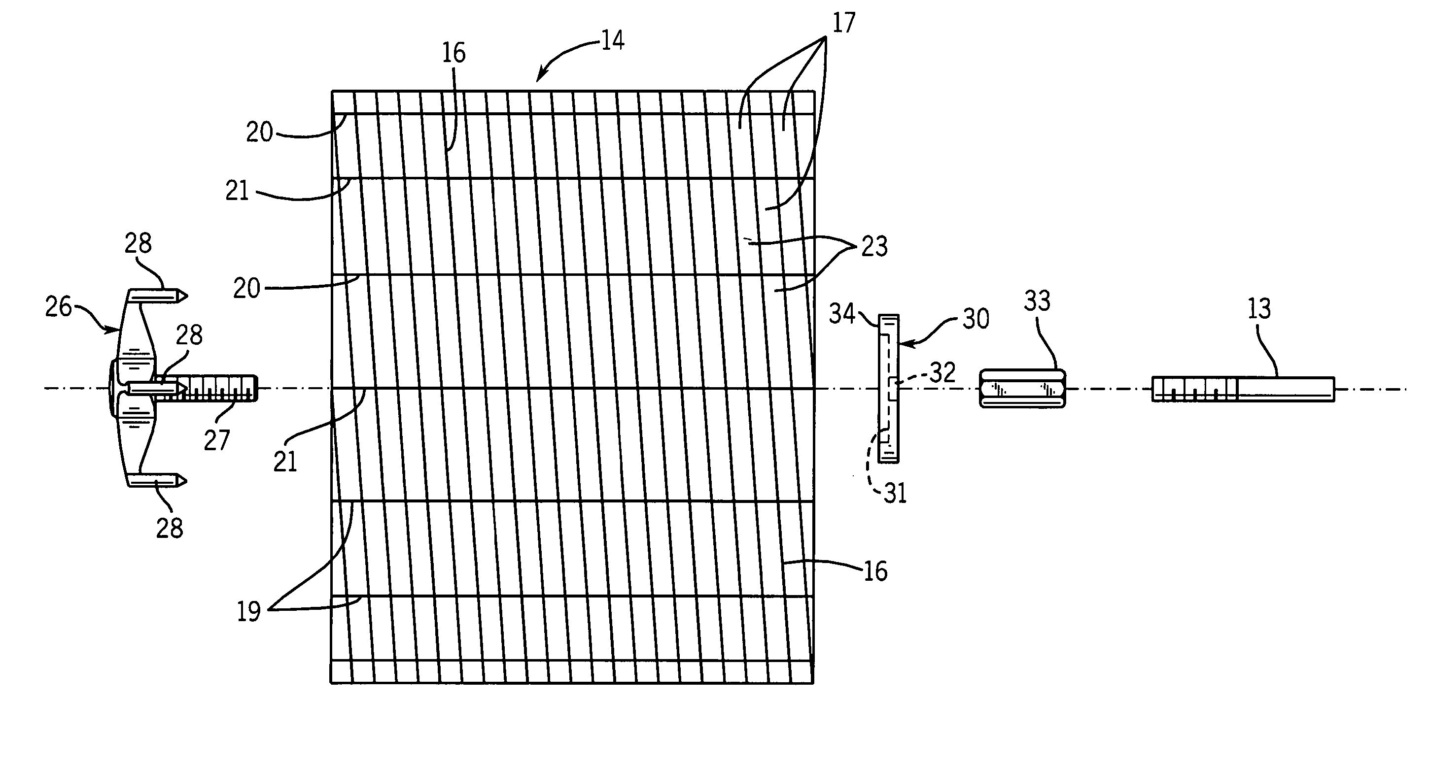
[0023] The buffing ball 10 of the preferred embodiment of the present invention is made from a monolithic cylindrical foam body 14 which may be of an suitable polymeric foam material typically used in buffing and polishing pads for various surface finishing operations. For example, an open cell polyurethane foam which may be reticulated or unreticulated is one suitable and presently preferred material. The cylindrical foam body 14 includes a central through bore 15 on the axis of the cyli...


PUM


Abstract

A buffing and polishing ball made of a compressible polymeric foam material is formed by slitting a body of foam material in a substantially uncompressed state (1) from an outside surface of the body in a direction generally perpendicular to the rotational axis and (2) on circumferentially spaced planes that extend generally radially from the outside surface of the body to define a plurality of foam fingers. A fastening system is used to compress and hold a center portion of the foam body in a direction along the rotational axis such that the uncompressed outer ends of the finger assume a generally spherical ball.

Description

CROSS-REFERENCE TO RELATED APPLICATION [0001] This application claims priority from U.S. Provisional Patent Application Ser. No. 60 / 526,680, filed Dec. 3, 2003.BACKGROUND OF THE INVENTION [0002] The present invention pertains to a rotary buffing device adapted to be attached to and driven by a powered operating tool or the like and, more particularly, to a buffing ball made at least partly of a plastic foam piece which is slit and compressed to form a ball for buffing, polishing and finishing a painted surface. [0003] Foam buffing pads are well known in the art and typically comprise circular, generally flat-faced pads attached to a circular backing plate which, in turn, is attached to a rotary or orbital powered operating tool. It is also known to make foam buffing pads by attaching a dense array of individual plastic foam fingers to a backing substrate such as is disclosed in U.S. Pat. No. 5,938,515. It is also known to make a buffing ball from a stack of thin circular layers of a...

Claims


Application Information

Patent Timeline
IPC IPC(8): A46B13/00B24B29/00B24D13/00B24D13/12
CPCA46B13/001B24D13/12B24B29/00
Inventor MCLAIN, SCOTT S.
Owner LAKE COUNTRY MFG
Why Eureka
Try Eureka