
Folding work table

a work table and folding technology, applied in the field of tables, can solve the problems of not having wheels or handles to facilitate the transportation of the table, no device to assist in the unfolding of the legs, and not having a handle to facilitate the transport of the table, etc., and achieves the effect of not being able to resist the reverse motion smoothly

Inactive Publication Date: 2005-06-09
BROOKS NOLAN
View PDF11 Cites 38 Cited by
  • Summary
  • Abstract
  • Description
  • Claims
  • Application Information

AI Technical Summary

Benefits of technology

[0021] In unfolding the table, the vast majority of the weight of the tabletop and any item attached to the tabletop is borne by the one-piece legs while the power assist actuators push the tabletop away from the free end of each one-piece leg, i.e., the end that is not attached to the tabletop. This allows the two two-piece legs (which have two pivotally attached segments) to unfold (a process which involves the rotational movement away from the tabletop of a second end of the segment which has a first end pivotally attached to the tabletop and also includes the second segment rotating from an initial position where such second segment is substantially parallel to the first segment and passes substantially adjacent to the first end of the first segment to a position substantially one hundred and eighty degrees from such first position) and, consequently, enables the free ends of the two-piece legs to be placed on a support surface, such as a floor, thereby rotating the tabletop to a horizontal position.
[0022] During the folding of the table, the power assist actuators aid in preventing the tabletop and any attached tool from too rapidly rotating toward the free ends of the two-piece legs.
[0023] A second facet of the improvement involves the attachment of a wheel near the free end of each two-piece leg; bending the free end of each two-piece leg away from the tabletop; and having the angle of the bend, the dimensions of the two-piece legs, and the dimensions and point of attachment for each wheel such that the free ends of the two-piece legs will hold the wheels above the support surface when the two-piece legs have been unfolded to support the tabletop while having such free ends higher than the bottom of the wheels and providing ground clearance for the free end that is substantially equal to the radius of the wheel near that free end when the table has been folded.

Problems solved by technology

The device of U.S. Pat. No. 3,646,895, however, has no device to assist in the unfolding of the legs for the table and also has no wheels or handle to facilitate transporting the table when the legs have been folded.
Significantly, however, a spring, unlike a piston within a cylinder, does not tend smoothly to resist reverse motion and has more tendency to break loose suddenly.
The process for folding and unfolding involves significant manipulation, which would render having a tool attached to either the main table or one of the auxiliary tables during the folding process difficult.
Although the Collapsible Portable Saw Stand of U.S. Pat. No. 6,578,856 can physically support a saw during the folding and unfolding process and possesses wheels to facilitate transportation of the folded stand and saw, it appears that considerable force would have to be used to unfold the stand when the saw is in place.

Method used


Image

  • Folding work table
  • Folding work table
  • Folding work table

Examples


Embodiment Construction

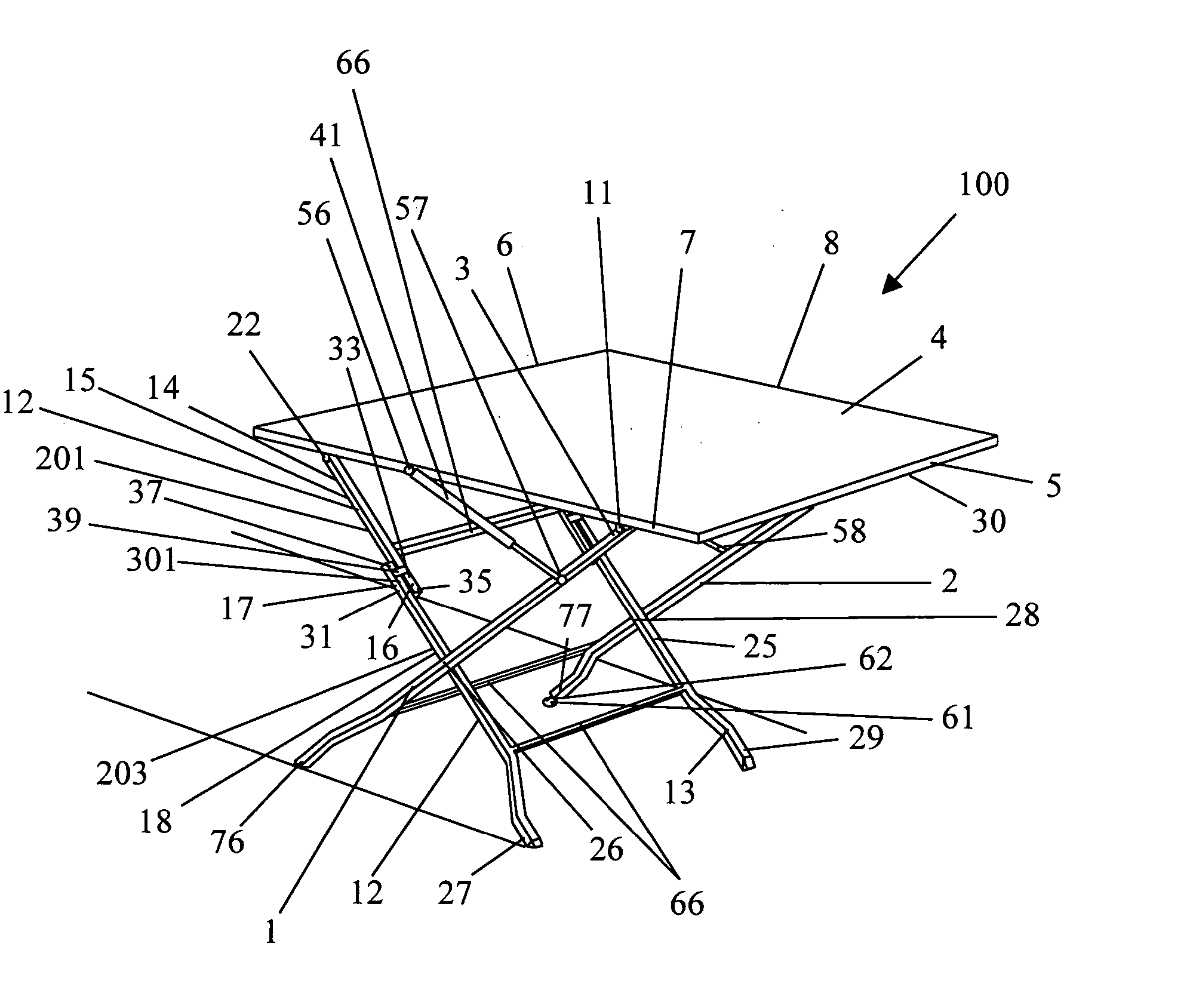
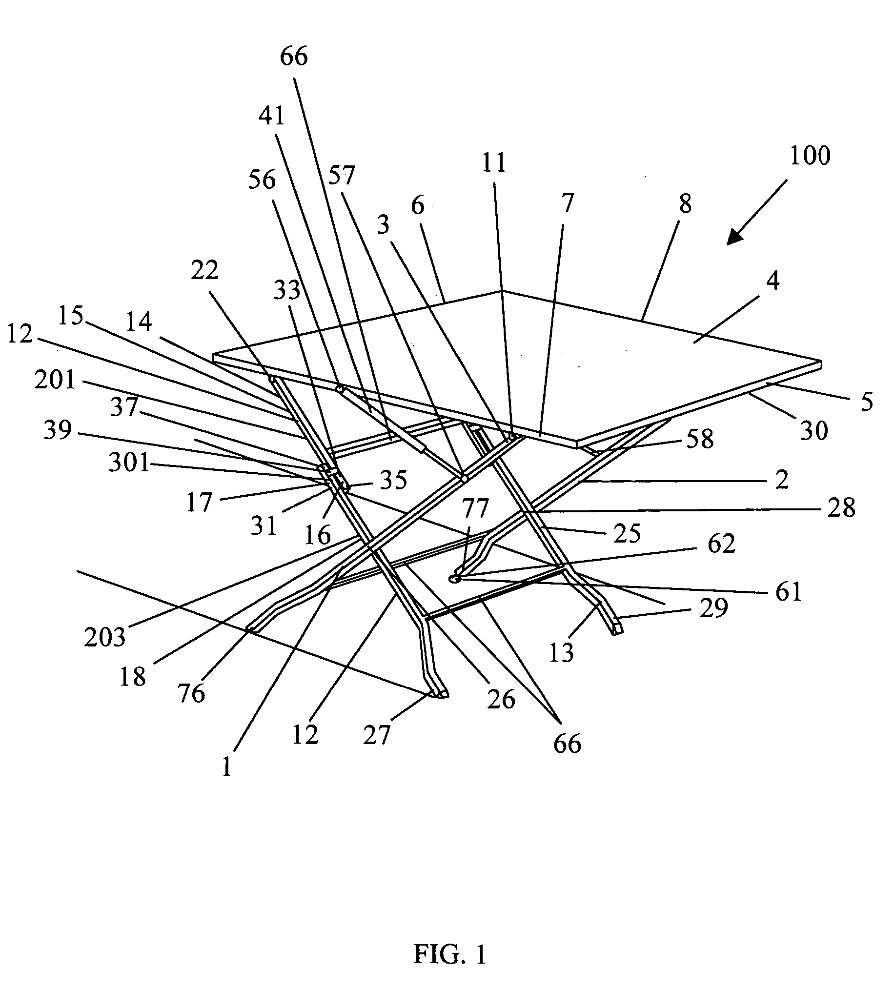
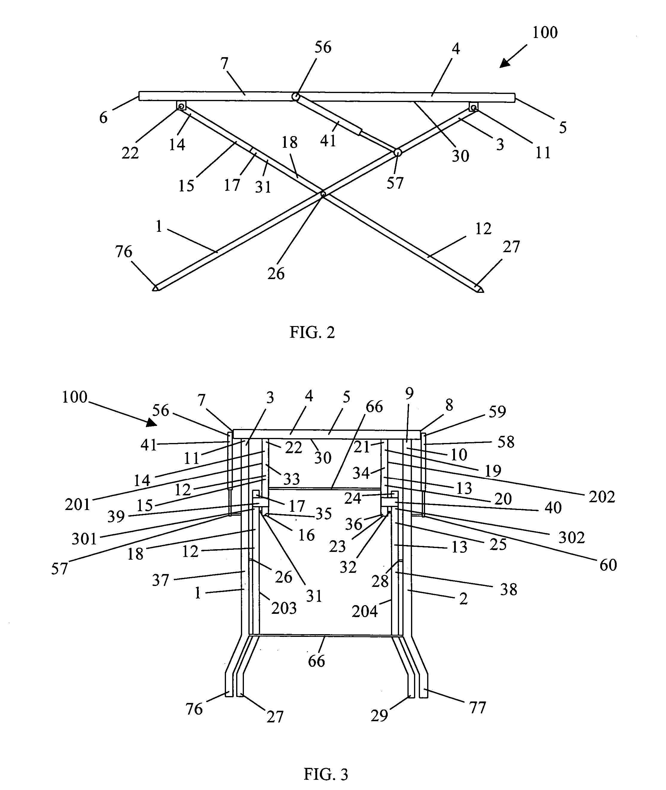
[0033] A first embodiment of the Folding Work Table includes, as illustrated in FIG. 1, FIG. 2, and FIG. 3, two one-piece legs 1, 2. A first end 3 of the first one-piece leg 1 is pivotally attached to a tabletop 4 having a first end 5, a second end 6, a first side 7, and a second side 8. Similarly, a first end 9 of the second one-piece leg 2 is pivotally attached to the tabletop 4 but at a point of attachment 10 which is closer to the second side 8 of the tabletop 4 than is the point of attachment 11 for the first end 3 of the first one-piece leg 1.

[0034] Two two-piece legs 12, 13 also are included. A first end 14 of a first segment 15 of the first two-piece leg 12 is pivotally attached to the tabletop 4. A second end 16 of the first segment 15 of the first two-piece leg 12 is pivotally attached to a first end 17 of a second segment 18 of the first two-piece leg 12. Likewise, a first end 19 of a first segment 20 of the second two-piece leg 13 is pivotally connected to the tabletop ...


PUM


Abstract

An improved folding table of the type having two one-piece legs pivotally attached to a tabletop and two two-piece legs pivotally attached to the tabletop with each one-piece leg pivotally connected to the two-piece leg that is on the same side of the table as the one-piece leg. The first primary improvement comprises a power assist actuator pivotally connected to the tabletop and to a first one-piece leg. Preferably, a second power assist actuator connects the tabletop and second one-piece leg. The second principal improvement comprises a first wheel rotatably connected near the free end of the first two-piece leg, a second wheel rotatably connected near the free end of the second two-piece leg, and the free ends of the two-piece legs being bent so that they support the table when the table is unfolded but do not interfere with the wheels of the table when the table is folded.

Description

BACKGROUND OF THE INVENTION [0001] 1. Field of the Invention [0002] This invention relates to a table the legs of which fold, especially a table upon which manual work, such as sawing, is performed. [0003] 2. Description of the Related Art [0004] U.S. Pat. No. 3,646,895, on line 69 of column 1 through line 3 of column 2, describes a Table with Folding Legs as follows: [0005]“Table 10 when in use is supported by two sets of legs 17 and 21. With respect to one set 17 of legs, each leg consists of two pivotally joined portions 16 and 18 which are joined by a pin fastener assembly 22. When the table is folded, as shown in FIGS. 1 and 3, these upper leg portions 18 nest in a position parallel to and alongside the lower leg portions 16. When this leg set 17 is extended, as shown in FIGS. 2 and 4, the respective portions 16 and 18 are pivoted into alignment and prevented from pivoting further than 180° by abutting a stop bracket 24 which is fastened to the upper leg portion 18 by using two...

Claims


Application Information

Patent Timeline
IPC IPC(8): A47B3/02
CPCA47B3/02
Inventor BROOKS, NOLAN
Owner BROOKS NOLAN
Features
  • Generate Ideas
  • Intellectual Property
  • Life Sciences
  • Materials
  • Tech Scout
  • Unparalleled Data Quality
  • Higher Quality Content
  • 60% Fewer Hallucinations
Learn More