Friction stir weld tool and method

Active Publication Date: 2005-06-09
THE BOEING CO
View PDF16 Cites 46 Cited by
  • Summary
  • Abstract
  • Description
  • Claims
  • Application Information

AI Technical Summary

Benefits of technology

[0008] The present invention provides a rotatable tool for friction stir welding a workpiece and an associated apparatus and method. The tool includes a first pin portion that extends from a shoulder and second pin portion that extends from the first pin portion. Advantageously, the first pin portion defines a contour surface opposite the shoulder. The contour surface, which mixes

Problems solved by technology

The mixing provided by the pin 12 is often insufficient t

Method used


Image

  • Friction stir weld tool and method
  • Friction stir weld tool and method
  • Friction stir weld tool and method

Examples


Example

[0023] The present invention now will be described more fully hereinafter with reference to the accompanying drawings, in which some, but not all embodiments of the invention are shown. Indeed, this invention may be embodied in many different forms and should not be construed as limited to the embodiments set forth herein; rather, these embodiments are provided so that this disclosure will be thorough and complete, and will fully convey the scope of the invention to those skilled in the art. Like numbers refer to like elements throughout.

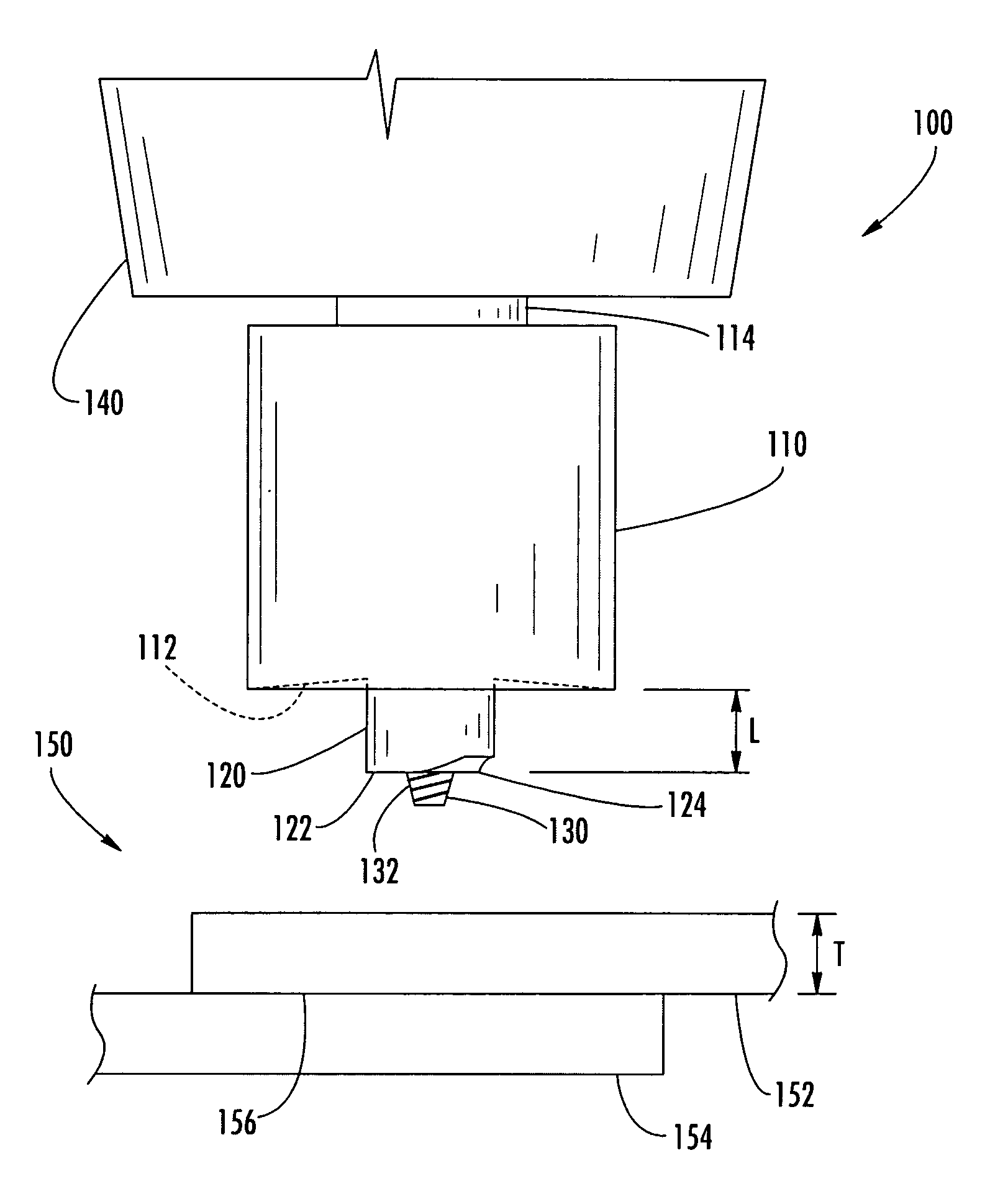
[0024] Referring now to the drawings and, in particular, to FIG. 2, there is shown an apparatus 100 for friction stir welding a workpiece 150 according to one embodiment of the present invention. The term “workpiece” is not meant to be limiting, and it is understood that the workpiece 150 can include one or more structural portions, each of which can be a separate structural member 152, 154. The structural members 152, 154 can be configured in vari...


PUM

PropertyMeasurementUnit
Thicknessaaaaaaaaaa
Thicknessaaaaaaaaaa
Lengthaaaaaaaaaa

Abstract

A rotatable tool for friction stir welding a workpiece and an associated apparatus and method are provided. The tool includes a first pin portion that extends from a shoulder and defines a contour surface opposite the shoulder. A second pin portion extends from the contour surface of the first pin portion. The contour surface, which mixes the material of the workpiece during welding, can increase the mixing of the material at the interface, thereby increasing the strength of the joint.

Description

BACKGROUND OF THE INVENTION [0001] 1) Field of the Invention [0002] The present invention relates to friction welding and, more specifically, to a tool and method for forming lap joints by friction stir welding. [0003] 2) Description of Related Art [0004] Friction stir welding is a process in which a rotating tool, such as a pin or probe, is urged into and / or through a workpiece, e.g., to join multiple structural members of the workpiece in a solid state or to repair cracks in a workpiece. As shown in FIG. 1, the pin 12 of the tool 10 typically extends from a shoulder 14, which can be flat, concave, or otherwise contoured, and the shoulder 14 is urged against the structural member 20 so that the pin 12 is urged into the structural members 20, 22. The pin 12 is then urged through the structural members 20, 22 to form a continuous weld joint 26. For example, according to one conventional friction stir welding process for forming a lap joint 26, a friction stir welding machine (not sho...

Claims


Application Information

Patent Timeline
IPC IPC(8): B23K20/12
CPCB23K20/1255
Inventor FULLER, CHRISTIAN B.MAHONEY, MURRAY W.BINGEL, WILLIAM H.
Owner THE BOEING CO
Why Eureka
Try Eureka