Burner for flare stack

Active Publication Date: 2016-10-06
HONEYWELL INT INC
View PDF3 Cites 3 Cited by
  • Summary
  • Abstract
  • Description
  • Claims
  • Application Information

AI Technical Summary

Benefits of technology

[0006]A flare gas burner and a process for disposing of a waste gas using same have been invented. The flare gas burner comprises a gas deflector

Problems solved by technology

While the Coanda tipped flare burners are effective at minimizing the production of smoke while combusting gas, some Coanda tipped flare burners produce a long flame.
The long flames can be problematic as they require more space t

Method used


Image

  • Burner for flare stack
  • Burner for flare stack
  • Burner for flare stack

Examples


Example

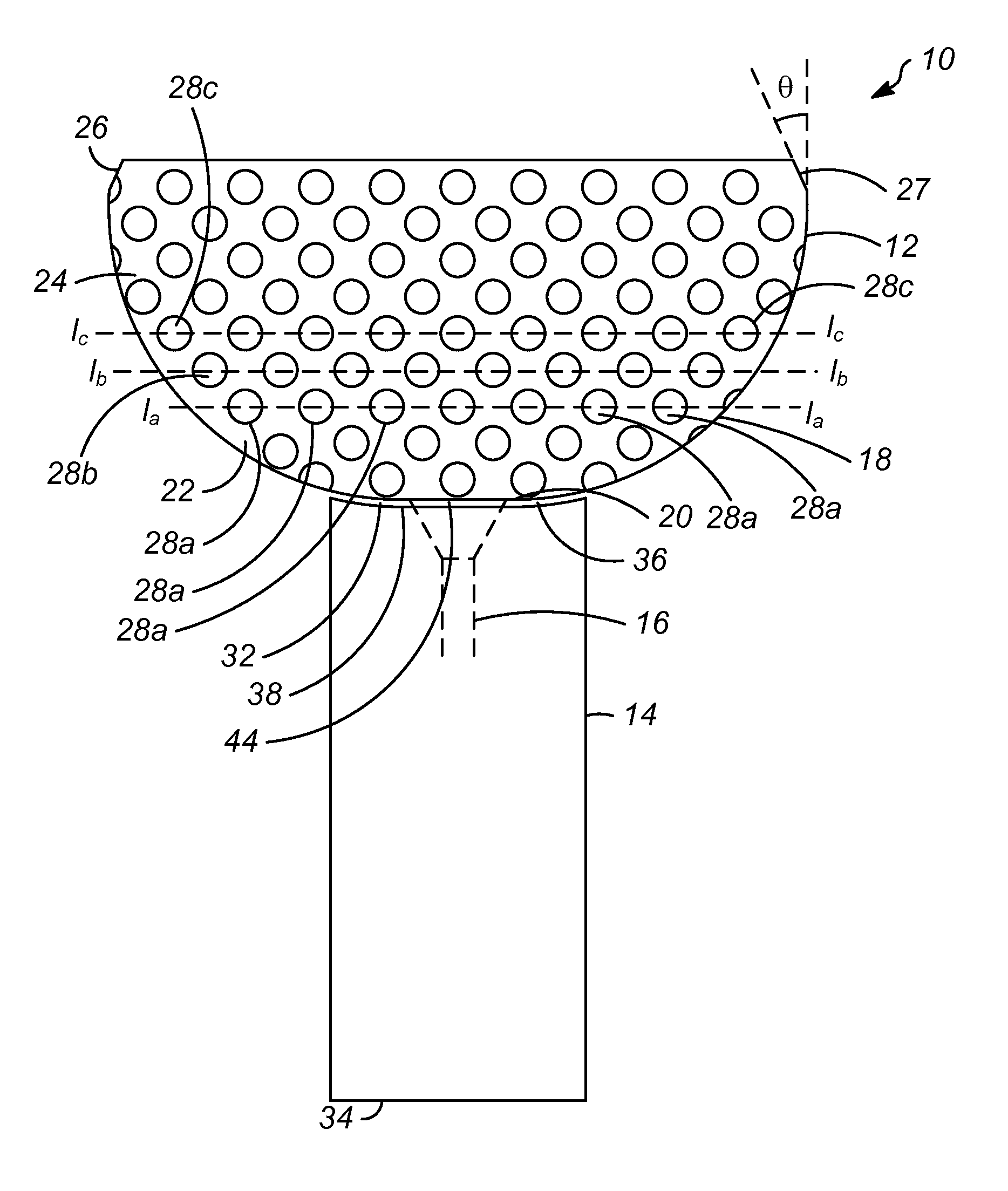
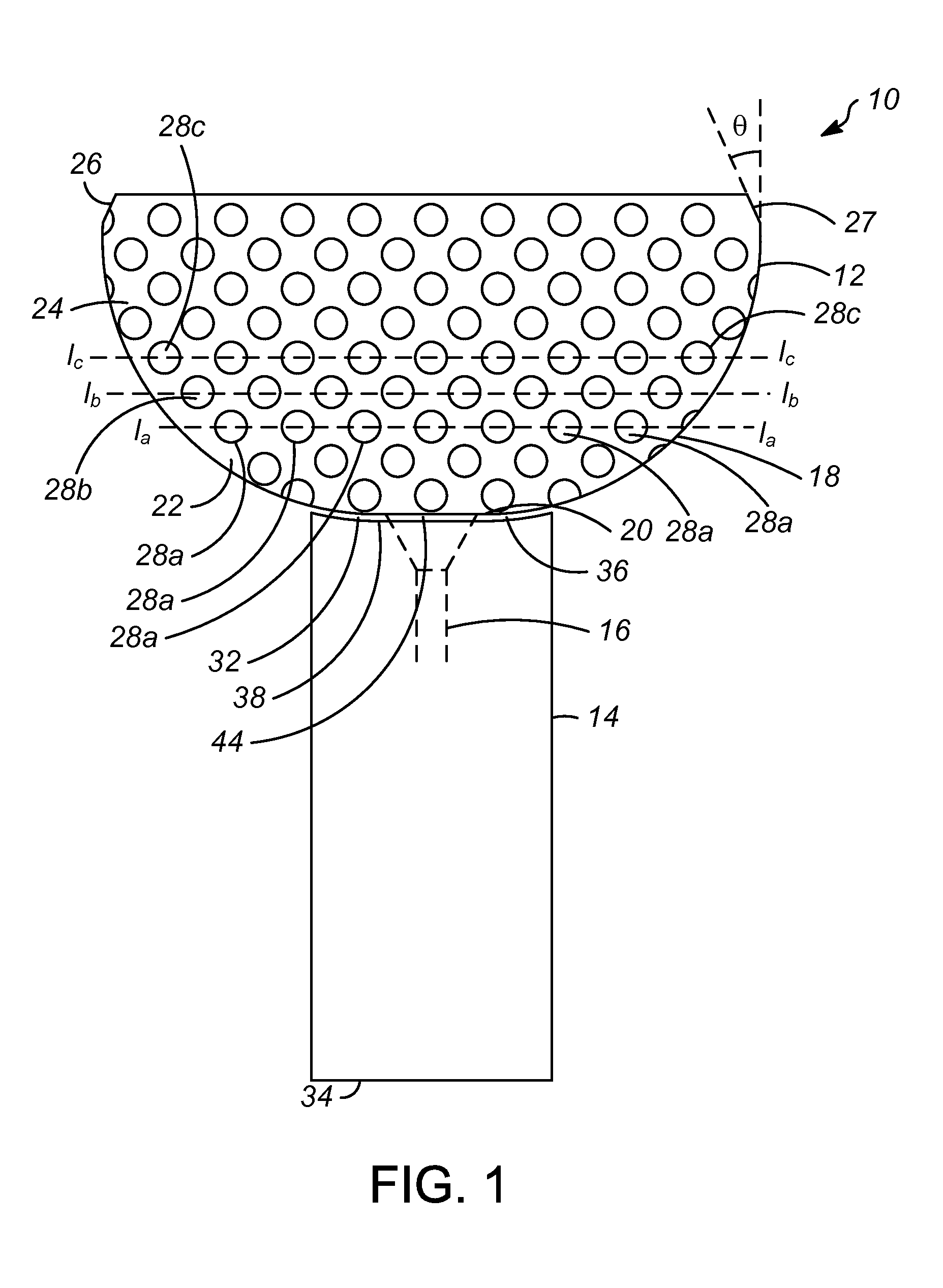
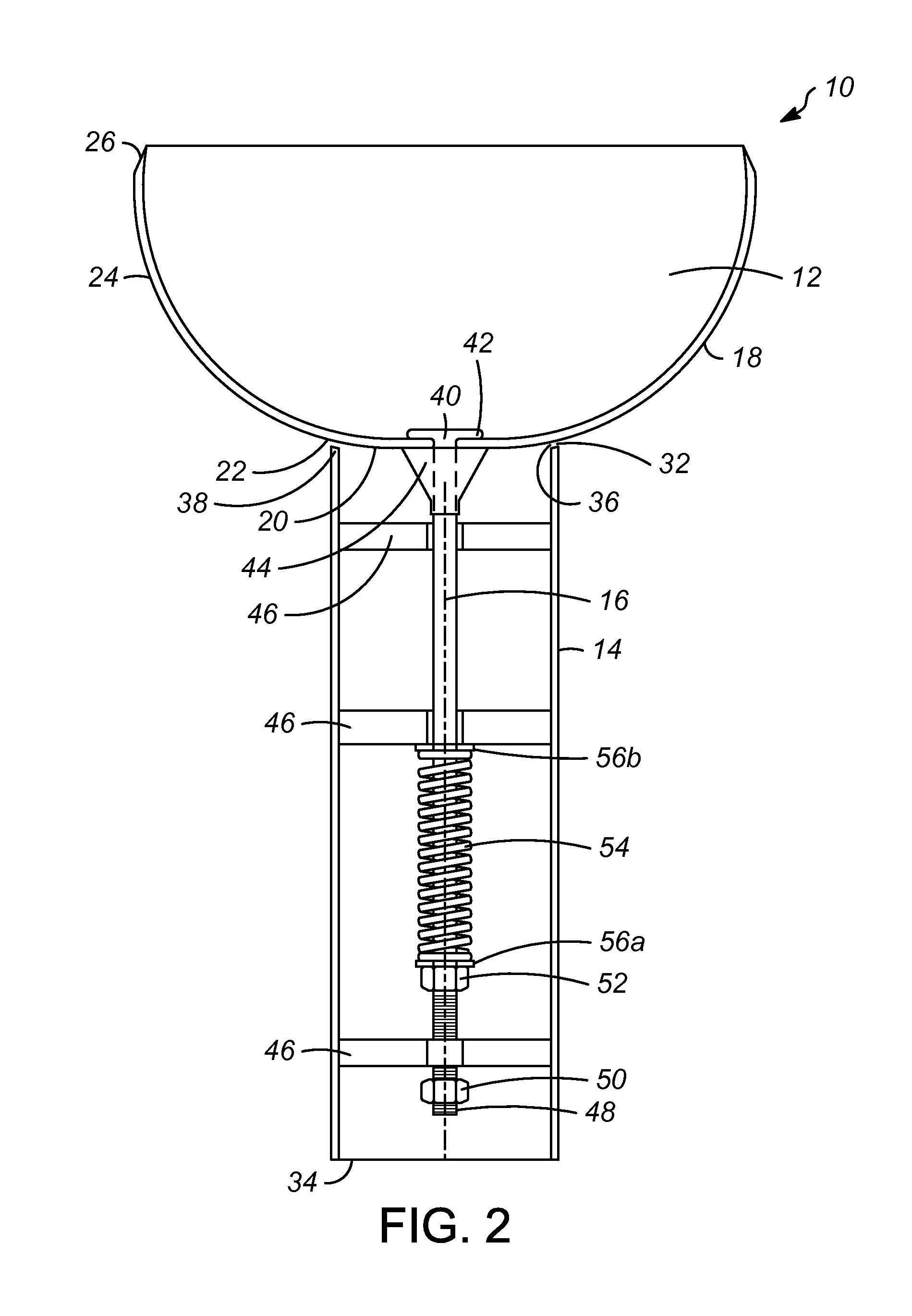
[0024]As mentioned above, a flare burner has been invented in which the burner provides the benefits of a Coanda tipped flare burner but with a shorter flame length and without producing as much noise. The outer surface of the Coanda surface includes a plurality of dimples. With this design, the drag force on the outer surface will be reduced by the Magnus effect, so the waste gas passing over the outer surface will obtain a higher velocity. This higher velocity of gas will inspire more air with it, which will increase the mixing of waste gas and air before combustion and will reduce the flame length produced by combustion. The dimple pattern is also believed to impact on the natural frequency of the semi-sphere, and thus is further believed that in some instances the noise can be reduced by 22% (from 75.3 dB to 58.5 dB).

[0025]With these general principles in mind, one or more embodiments of the present invention will be described with the understanding that the following descriptio...


PUM


Abstract

A flare gas burner and a process for disposing of a waste gas using such a burner. The burner has a rounded outer surface that includes a plurality of dimples. The dimples increase the mixing of the waste gas and ambient air prior to combustion. The flare gas burner may have a diameter of 0.61 m and between 300 and 400 dimples. The flare gas burner may comprise a cast material.

Description

FIELD OF THE INVENTION[0001]This invention relates generally to a flare burner for a flare stack, and more particularly to a flare burner that produces less noise and a shorter flame than conventional flare burners.BACKGROUND OF THE INVENTION[0002]Flares have traditionally been utilized for burning and exhausting combustible gases. Commonly, flares are mounted on flare stacks and located at production, refining, and processing plants for disposing of flammable waste gases or other flammable gas streams, which are diverted for any reason, including but not limited to venting, shut-downs, upsets, and / or emergencies. Primarily, flare stacks are used for venting unwanted waste gas streams from a facility.[0003]In order to produce a flame without producing smoke, many flare burners include a tulip shaped Coanda tip. Coanda tips have been used in flares with high flow rates and pressures to cause the adherence of the waste gas to the surface. The negative pressure and viscous forces cause...

Claims


Application Information

Patent Timeline
IPC IPC(8): F23G7/08
CPCF23N2041/12F23G7/08F23D2900/14021F23N2241/12
Inventor NOMAN, SHIBLEEKRAUS, KURT EDWARDSHANNON, MATTHEW L.
Owner HONEYWELL INT INC
Why Eureka
Try Eureka