Display device, driver circuit therefor, and method of driving same

a technology of driver circuit and display device, which is applied in the direction of electric digital data processing, instruments, computing, etc., can solve the problems of large voltage follower circuit, high impedance, complex circuitry, etc., and achieve high-quality display, circuit area, and extremely small voltage values of data electrodes

Active Publication Date: 2005-06-09
RENESAS ELECTRONICS CORP
View PDF10 Cites 54 Cited by
  • Summary
  • Abstract
  • Description
  • Claims
  • Application Information

AI Technical Summary

Benefits of technology

[0045] According to the present invention, a plurality of data electrodes are driven in time-division fashion by a single voltage follower circuit and the data electrodes are driven by the grayscale selecting circuits even after a prescribed voltage has been attained by the voltage follower circuit. As a result, a deviation in the voltage values of the data electrodes can be kept extremely small. Furthermore, it is possible to correct for any variance ascribable to the offset voltage of the voltage follower circuit. Accordingly, the circuit area of the data electrode driver circuit can be reduced and a high-quality display can be obtained by eliminating display unevenness.

Problems solved by technology

There are many circuit elements because the circuitry is complicated.
Since the circuit area occupied by the phase-compensated capacitor is large, the voltage follower circuit becomes large in size.
On the other hand, when data electrodes are driven in time-division fashion, a period over which the data electrodes take on a high impedance occurs.
If there is a small amount of leakage into a data electrode, therefore, voltage fluctuates and display unevenness occurs.
However, such a technique has not been disclosed heretofore.

Method used


Image

  • Display device, driver circuit therefor, and method of driving same
  • Display device, driver circuit therefor, and method of driving same
  • Display device, driver circuit therefor, and method of driving same

Examples


first embodiment

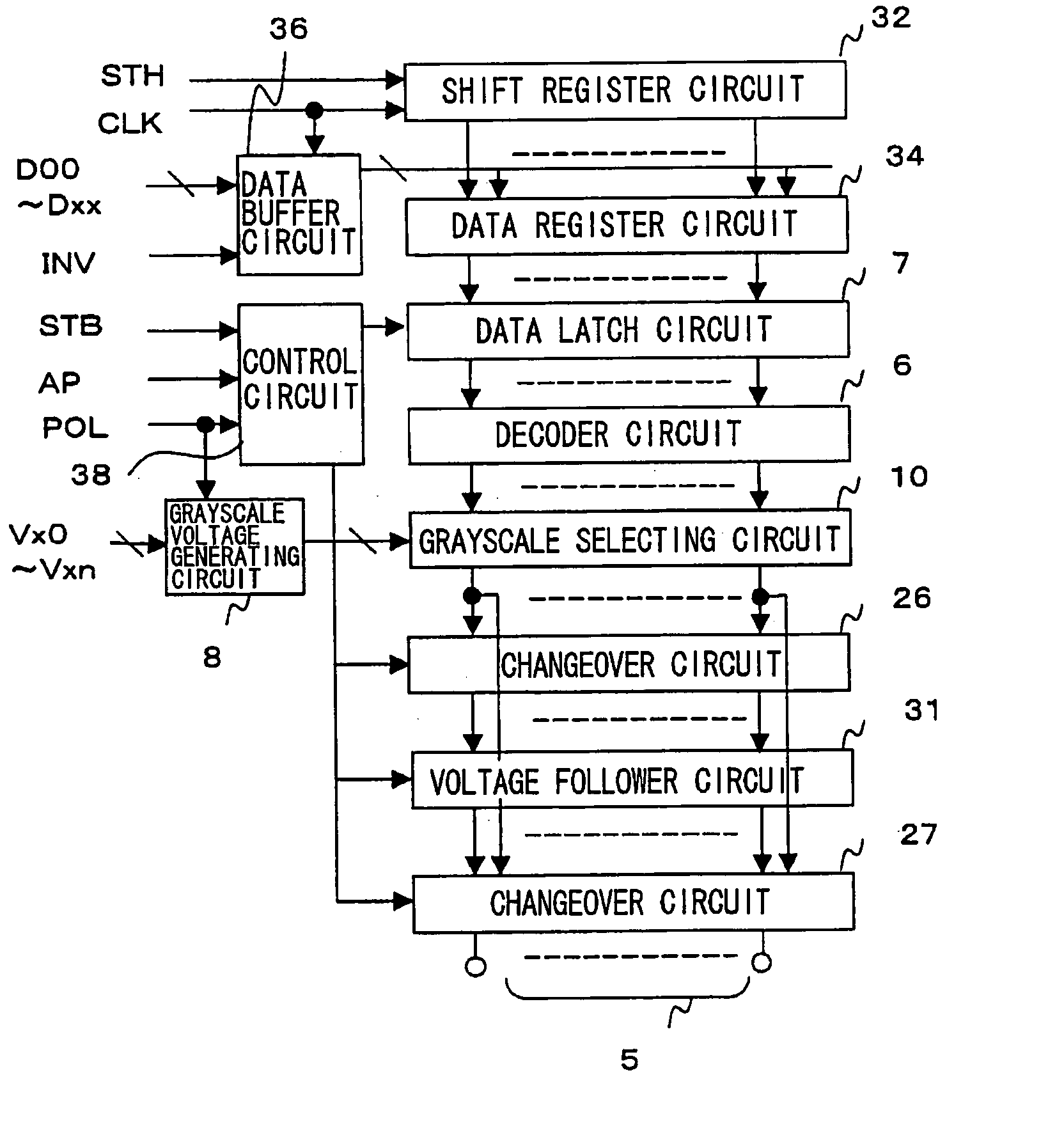
[0078] The circuitry of the main components of the data electrode driving circuit will be described next. FIG. 4 is a circuit diagram of the main components of the data electrode driving circuit according to the FIG. 4 illustrates a case where the data electrodes are three in number (5R, 5G, 5B). Decoder circuits 6R, 6G, 6B, grayscale selecting circuits 1R, 1G, 1B, switches 2R, 2G, 2G, switches 3R, 3G, 3B and switches 4R, 4G, 4B are provided in correspondence with electrodes SR, 5G, 5B, respectively. Accordingly, the description will be rendered only with regard to data electrode 5R. It should be noted that the circuitry of the main components also includes the grayscale voltage generating circuit 8 and the voltage follower circuit 31 that can be deactivated by cutting off the bias current.

[0079] The output of the decoder circuit 6R is input to the grayscale selecting circuit 1R. In accordance with the output of the decoder circuit 6R, the grayscale selecting circuit 1R selects a p...

fourth embodiment

[0108] In the fourth embodiment, it is assumed that mutually adjacent data electrodes are driven alternatingly by a voltage “+” on the positive-electrode side and a voltage “−” on the negative-electrode side, as illustrated in FIG. 10. Accordingly, with dot inversion, the polarities of mutually adjacent data electrodes differ (e.g., see R1 and G1, G1 and B1). Consequently, 64 levels of the grayscale are output simultaneously for each of the positive and negative electrodes. This means that grayscale voltages of 128 levels are required.

[0109]FIG. 11 is a circuit diagram of the main components of a data electrode driving circuit according to the fourth embodiment of the present invention. The main points in FIG. 11 that differ, in terms of structure, from FIG. 4 in the first embodiment will be described. A grayscale voltage generating circuit 8A generates a grayscale voltage signal 8P on the positive-electrode side and a grayscale voltage signal 8N on the negative-electrode side. A de...


PUM

PropertyMeasurementUnit
currentaaaaaaaaaa
voltageaaaaaaaaaa
offset voltageaaaaaaaaaa

Abstract

Disclosed is a driver circuit for driving a display device. The driver circuit includes N-number (where N is a natural number) of grayscale selecting circuits, which correspond to N-number of data electrodes, each for selecting one grayscale voltage from among a plurality of grayscale voltages in accordance with an image signal; one voltage follower circuit for subjecting the grayscale voltages, which have been selected by the grayscale selecting circuits, to an impedance conversion to thereby drive the data electrodes; and a changeover control circuit for exercising control so as to divide one horizontal interval into at least (N+1)-number of intervals, drive a Kth data electrode by the output of the amplifier circuit by inputting only an output of a Kth grayscale selecting circuit to the amplifier circuit in a Kth (K=1 to N) interval, and drive the Kth data electrode by the output of the Kth grayscale selecting circuit in at least some intervals other than the Kth interval.

Description

FIELD OF THE INVENTION [0001] This invention relates to a display device, a driver circuit for driving the display device, and a method of driving the same. More particularly, the invention relates to a driver circuit for driving data electrodes in a display device having pixel circuits arranged in the form of a matrix, and to the driving method. BACKGROUND OF THE INVENTION [0002] A display device for a portable electronic device such as a mobile telephone is required to consume little power and to exhibit a high image quality. Accordingly, it is desired that the driver circuit of the display device consume little power and be small in size. [0003] The specification of Japanese Patent Kokai Publication No. JP-P2002-215108A (see FIG. 13 of the specification) discloses a circuit whereby a display device for a portable electronic device such as a mobile telephone is driven with little consumption of power. [0004]FIG. 16 is a block diagram of a 6-bit (64-gray-level) data electrode drivi...

Claims


Application Information

Patent Timeline
Patent Type & Authority Applications(United States)
IPC IPC(8): G02F1/133G09G3/20G09G3/30G09G3/36G09G5/10
CPCG09G2310/027G09G3/3688G09G3/20G09G3/30G09G3/36
Inventor HASHIMOTO, YOSHIHARU
Owner RENESAS ELECTRONICS CORP
Why Eureka
Try Eureka