
Electronically modulated prism

a technology of electromagnetic modulation and prism, applied in the field of electromagnetic modulation prism, can solve the problems of signal “smearing” in time, unsatisfactory effects, and true time delay (ttd) experienced progressively across the wavefront, and achieve the effect of fine steering of the incident beam

Active Publication Date: 2005-06-09
NORTHROP GRUMMAN SYST CORP
View PDF1 Cites 16 Cited by
  • Summary
  • Abstract
  • Description
  • Claims
  • Application Information

AI Technical Summary

Benefits of technology

[0018] Therefore, by selectively applying the electric field to the electrode pads and the common electrode across the bulk crystal, local phase shifts of the incident beam are induced and accumulated along the propagation path of the incident beam. The method further comprises a step of adjusting the intensity of the electric field applied at various positions of the bulk crystal. Therefore, a fine steering of the incident beam can be achieved. In one embodiment of the present invention, the intensity of the electric field can be independently adjusted at each of the various positions.

Problems solved by technology

However, because these approaches lack the phase range, or “stroke” to modulate the whole wavefront sufficiently steer the incident light beam at a significant angle, the steering elements are subdivided into smaller arrays that operate on subaperture portions of the larger wavefront.
The subaperture division leads to undesired effects.
One of the most vexing issues associated with the subaperture effect is the true time delay (TTD) experienced progressively across the wavefront.
In the free-space optical communication missions or in any mission concerned with very fast ( about tens of Gb per second) modulation of waveforms, phasing of subapertures will cause some parts of the wavefront to reach the receiver detector at a later time than other parts of the wavefront, leading to signal “smearing” in time.

Method used


Image

  • Electronically modulated prism
  • Electronically modulated prism
  • Electronically modulated prism

Examples


Embodiment Construction

[0030] The present invention provides an electronically modulated prism (EMP) used in a beam steering system to achieve ultra-fast, agile and fine steering. The electronically modulated prism proposed in the present invention steers an incident beam in a similar fashion that a glass prism does, such that rather than phasing subapertures by modulo 2π, the electronically modulated prism accumulates phase along the wavefront as whole. This facilitates agile steering at least over a fine angle without concern for additional diffraction, higher divergence or true time delay issues.

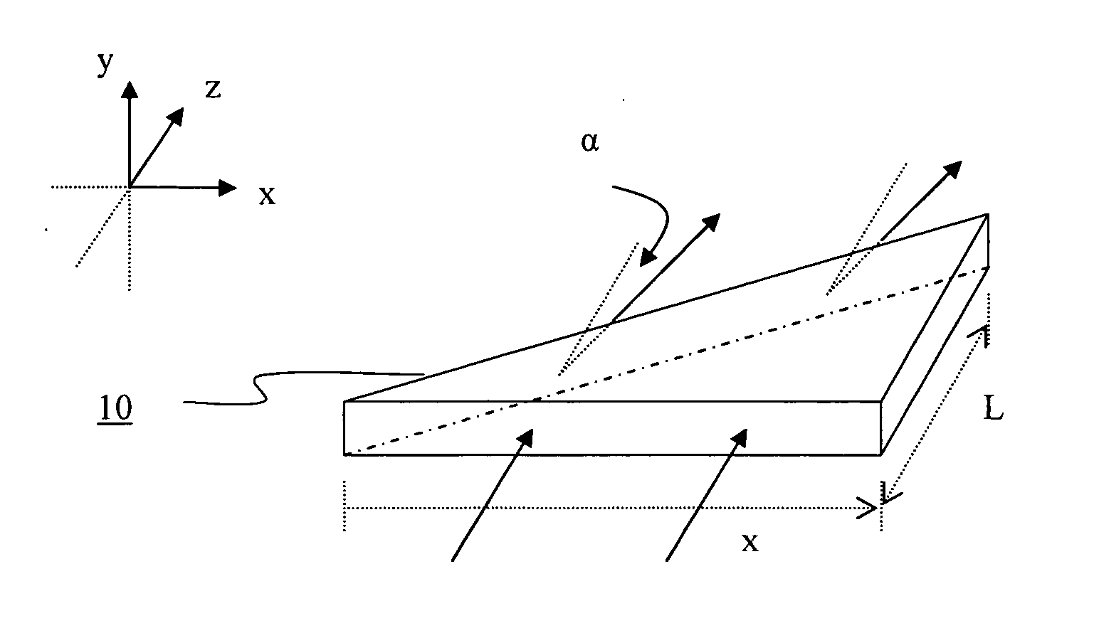
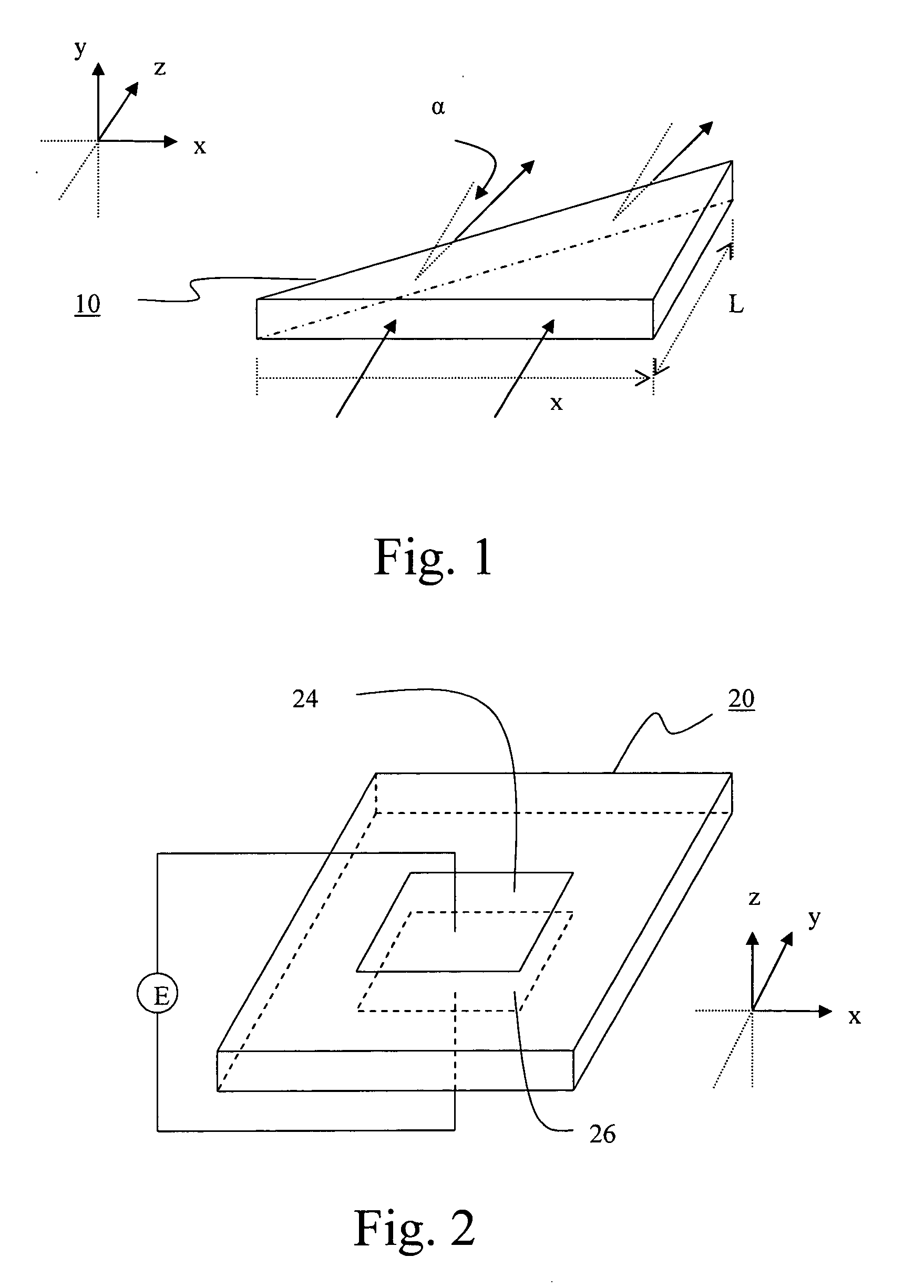
[0031]FIG. 1 shows a glass or crystal is shaped into an optimally oriented prism 10. The shape of the prism 10 provides a gradient of optical-path difference (OPD) across the wavefront of the incident beam. Assuming that the index of refraction of the prism 10 is n, and the length of the prism through which the light beam transmits is L(x), the optical-path difference OPD(x) is:

OPD(x)=nL(x)  (2),

where L(x) is...


PUM


Abstract

An electronically modulated prism, having a bulk crystal, a plurality of electrode pads formed on a top surface of the bulk crystal, and a common electrode formed on a bottom surface of the bulk crystal. The bulk crystal is optically isotropic with zero electric field applied thereto and optically anisotropic when subjected to a non-zero electric field. More specifically, the bulk crystal between each of the electrode pads and the common electrode has an index of fraction altered proportionally to the electric field applied thereto, such that an incident beam propagate through the crystal is modulated with an accumulated phase shift.

Description

CROSS-REFERENCE TO RELATED APPLICATIONS [0001] Not Applicable STATEMENT RE: FEDERALLY SPONSORED RESEARCH / DEVELOPMENT [0002] Not Applicable BACKGROUND OF THE INVENTION [0003] The present invention relates in generally to an electronically modulated prism, and more particularly, to a scalable and agile beam-steering device that uses an electronically modulated prism. [0004] Precise and controllable delivery of light beams or other guided modes to a desired location has been an important topic with telecommunication, military and other general industrial applications. In the military application, the beam steering is a critical technique in an airborne, active, electro-optical (EO) system. Examples of missions requiring the beam steering technique include self-protection, such as infrared countermeasures (IRCM) and damage-and-degrade (D2) applications, targeting, intelligence, surveillance, and reconnaissance (ISR), infrared search and track (IRST), laser radar (LADAR), vibrometry, and...

Claims


Application Information

Patent Timeline
IPC IPC(8): G02B5/04G02F1/29
CPCG02F1/292G02B5/04
Inventor CICCHIELLO, JAMES M.
Owner NORTHROP GRUMMAN SYST CORP
Learn More