Sealed header and method of making

a header and sealing technology, applied in the direction of electrical apparatus construction details, electrical apparatus casings/cabinets/drawers, support structure mounting, etc., can solve the problem that the design proves difficult to properly seal

Inactive Publication Date: 2005-06-09
TE CONNECTIVITY CORP
View PDF12 Cites 58 Cited by
  • Summary
  • Abstract
  • Description
  • Claims
  • Application Information

AI Technical Summary

Problems solved by technology

The module described in U.S. Pat. No. 5,998,738 is difficult to manufacture, and due to the fact that the flexible film is wrapped around the housing member, the design proves difficult to properly seal.

Method used


Image

  • Sealed header and method of making
  • Sealed header and method of making
  • Sealed header and method of making

Examples


Embodiment Construction

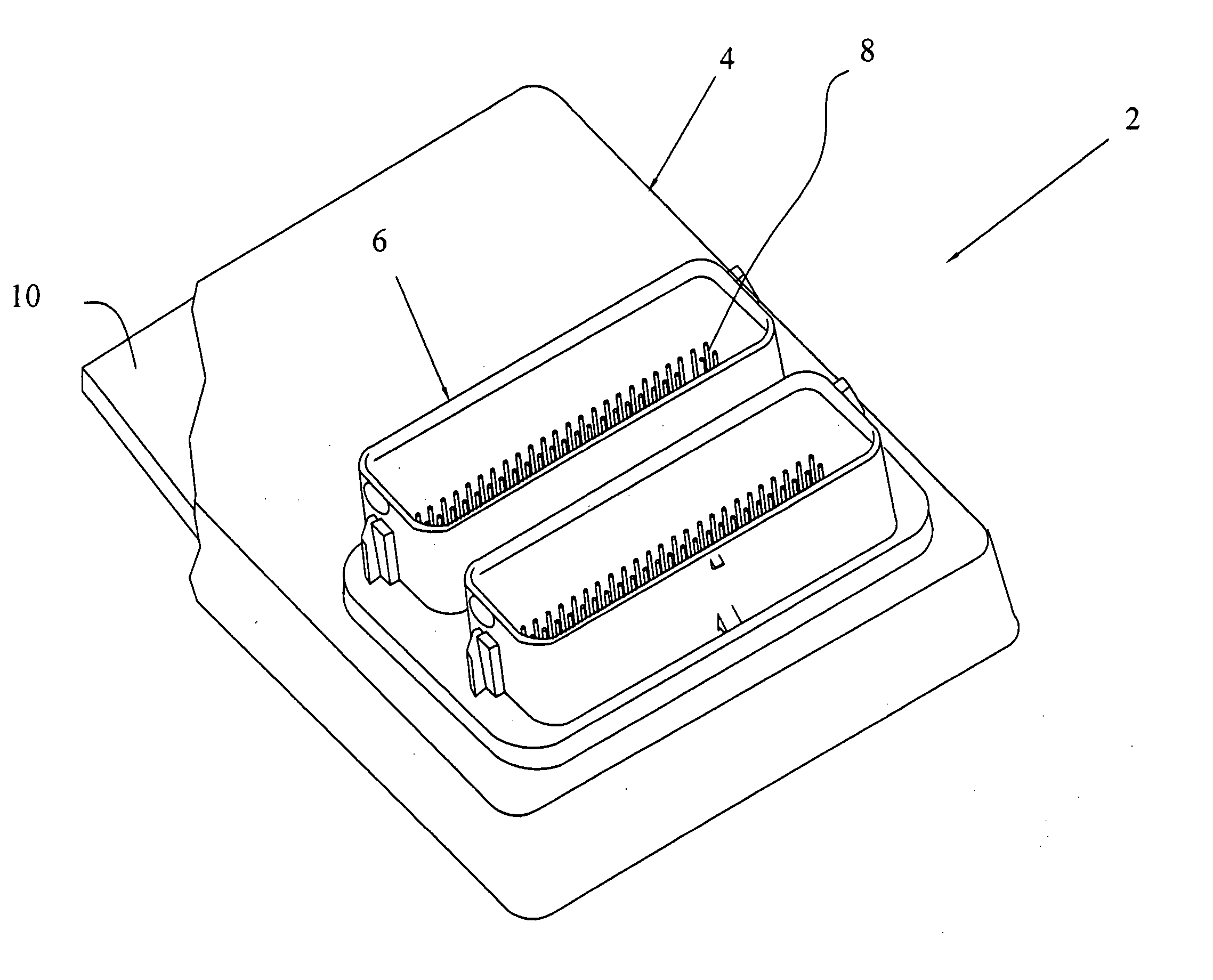
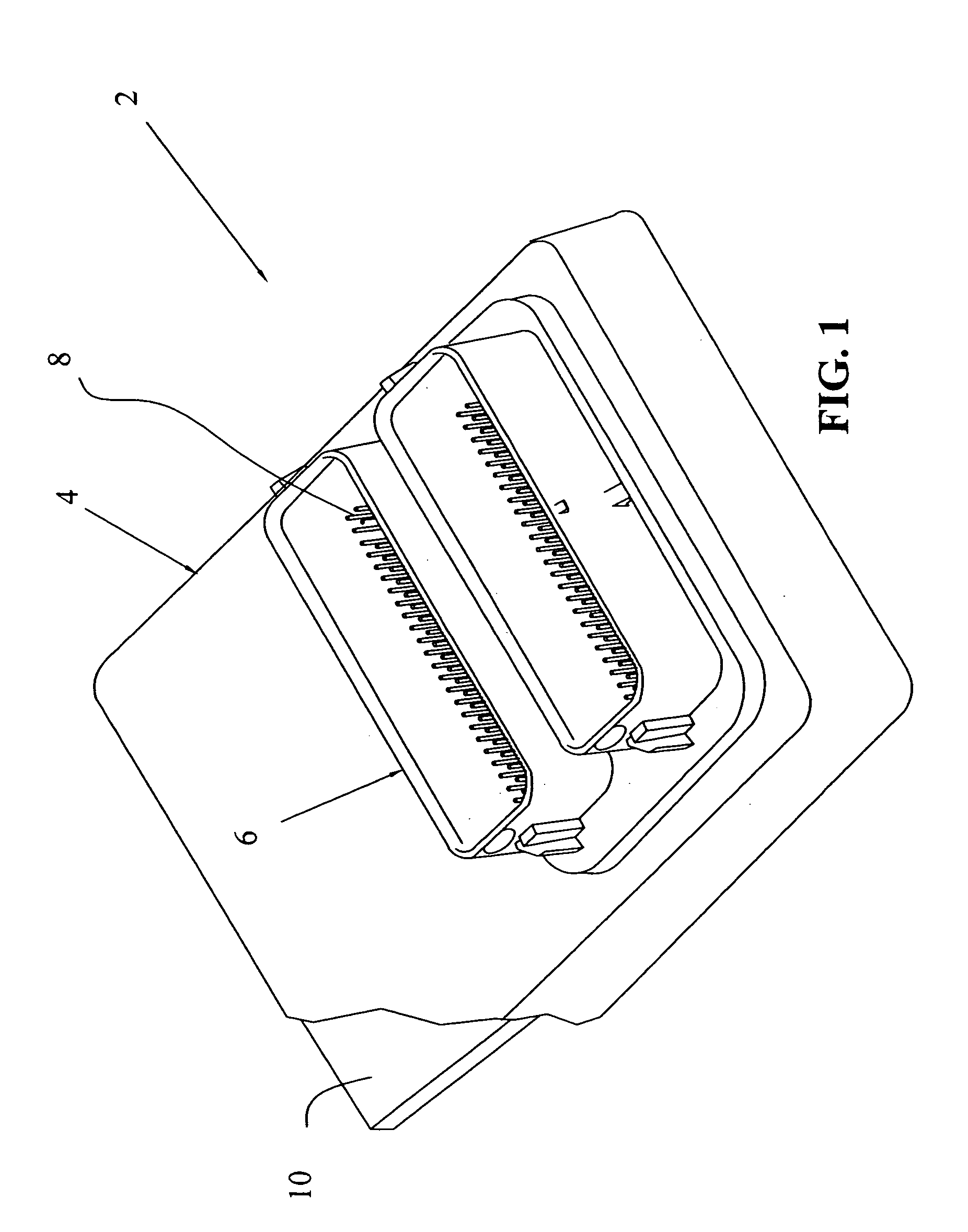
[0030] With respect first to FIG. 1, an electronic module is shown at 2, which is generally comprised of a casing 4, an electrical connector header 6 having electrical terminals 8, which are then interconnected to printed circuit board 10. It should also be appreciated that the printed circuit board 10 is confined within the cavity of the casing 4 and can be sealed by various methods as described herein. It would also be appreciated that the casing would be comprised of a material suitable for use in an engine compartment, such as a cast metal material, for example, cast aluminum.

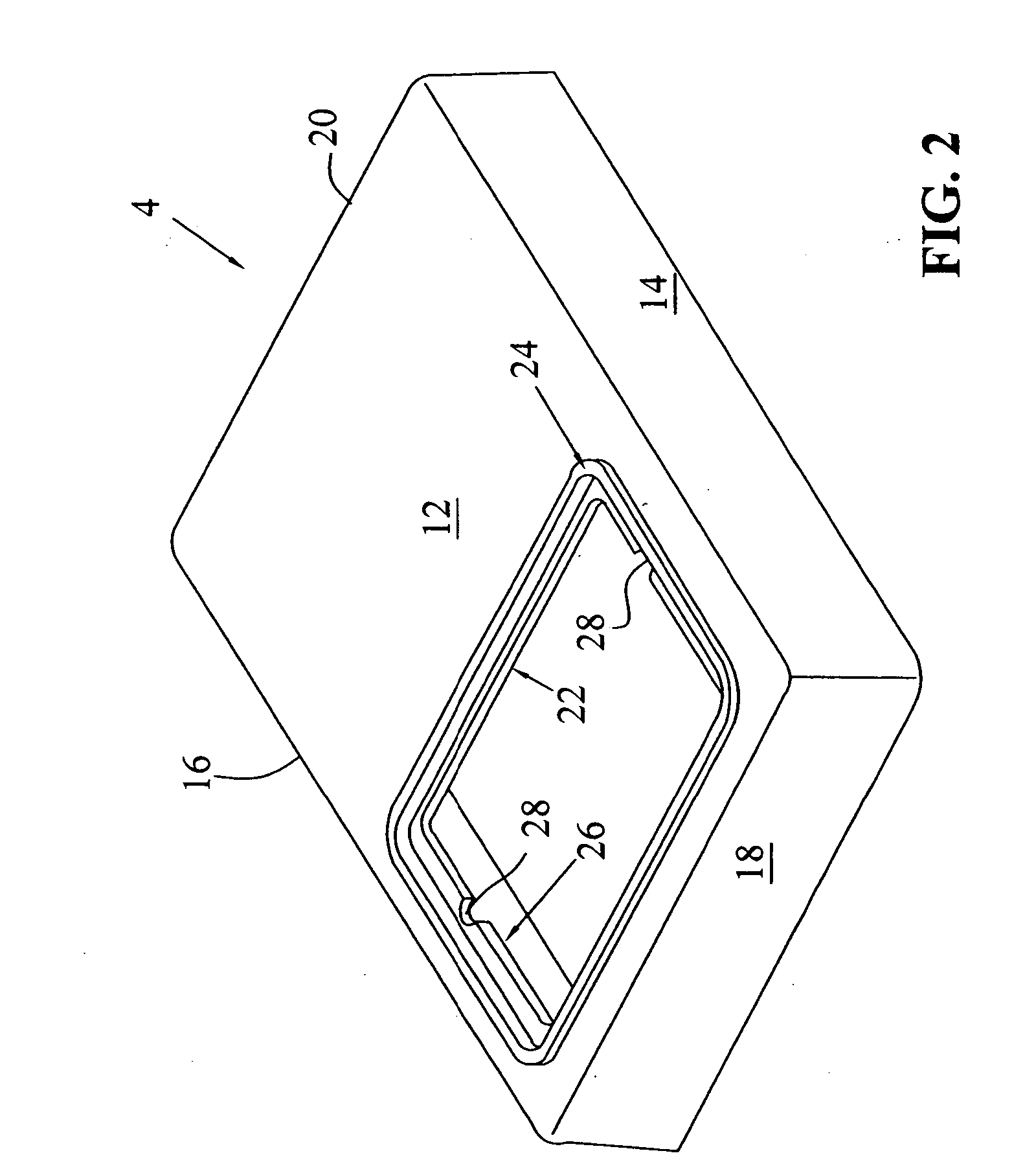
[0031] With reference now to FIG. 2, the casing 4 will be described in greater detail. Casing 4 is generally defined by a rectangular-shaped member having a major planar surface at 12, side walls 14 and 16, and end walls 18, 20. As also shown in FIG. 2, an opening 22 is defined through surface 12 and is bounded by a peripheral sealing wall 24. It should also be appreciated that the volume within casing 4 b...


PUM


Abstract

An electronic module (2) comprises casing 4, and header 6 with a printed circuit board 10 positioned within a cavity 26 of casing 4. Connector 6 includes terminals 8, which allow for electrical connection for a mating connector, but also include compliant portions 54 which form the mechanical and electrical connector to printed circuit board 10. Compliant portions 54 together with an adhesive 62 provide for the bonded connection between header 6 and printed circuit board 10. Gasket 60 further provides a peripheral seal between casing 4 and header 6.

Description

FIELD OF THE INVENTION [0001] The invention relates to an electronic control module and a method for making the same. BACKGROUND OF THE INVENTION [0002] It is quite common in the automotive industry to provide sealed electronic control modules. Such modules are useful for controlling any of the engine functions, such as air fuel ratio, ignition, fuel injection, and the like. Typically, the modules include a housing or casing having a substrate therein, positioned therein, where the substrate includes electronic components to control the various functions. The substrate could comprise a printed circuit board or flexible substrate. The substrate would include a connection mechanism adjacent to an edge thereof, where the connector is positioned adjacent an opening of the casing. The casing would thereafter be positionable adjacent to the engine, where the connector on the control module would complement a connector on the engine device to be monitored / controlled. [0003] Such is the cas...

Claims


Application Information

Patent Timeline
Patent Type & Authority Applications(United States)
IPC IPC(8): H05K5/00H05K5/04H05K5/06
CPCH05K5/0069
Inventor KANE, VINCENT
Owner TE CONNECTIVITY CORP
Why Eureka
Try Eureka