Radiographic image diagnosis device

a radiographic image and diagnostic device technology, applied in the field of xray diagnosis equipment, to achieve the effect of facilitating comparison observation

Inactive Publication Date: 2005-06-09
HITACHI MEDICAL CORP
View PDF4 Cites 8 Cited by
  • Summary
  • Abstract
  • Description
  • Claims
  • Application Information

AI Technical Summary

Benefits of technology

[0012] Further, according to another aspect of the present invention, for example, the output data value of the tenth image as shown in FIG. 5 when the inherent initial low output build up characteristic of the X ray flat panel detector is saturated is used as a reference and an output data value correction table for the respective first, second, . . . , nth images (n is an integer more than 1) is prepared in advance and stores the same in a memory, and when taking X ray images and display the same, after correcting the respective image output data by making use of the correction tables and by outputting the corrected image output data on a display, X ray images of uniform brightness which facilitates comparison observation are obtained.

Problems solved by technology

However, in the field of X ray detection, it is not preferable in view of X ray exposure of an object to irradiate X ray to the object prior to image taking irradiation.

Method used


Image

  • Radiographic image diagnosis device
  • Radiographic image diagnosis device
  • Radiographic image diagnosis device

Examples


Embodiment Construction

[0018] Herein below, an embodiment of the present invention will be explained with reference to drawings.

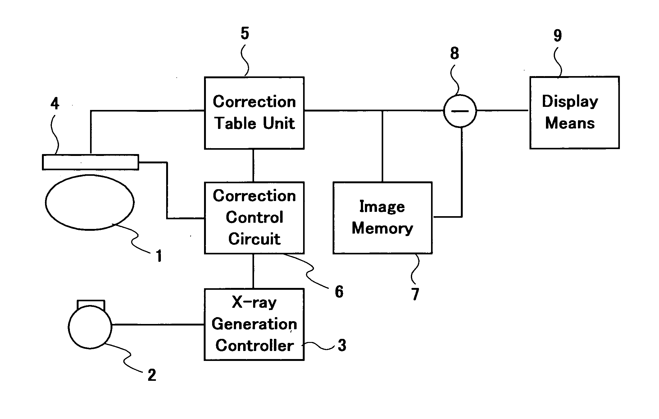
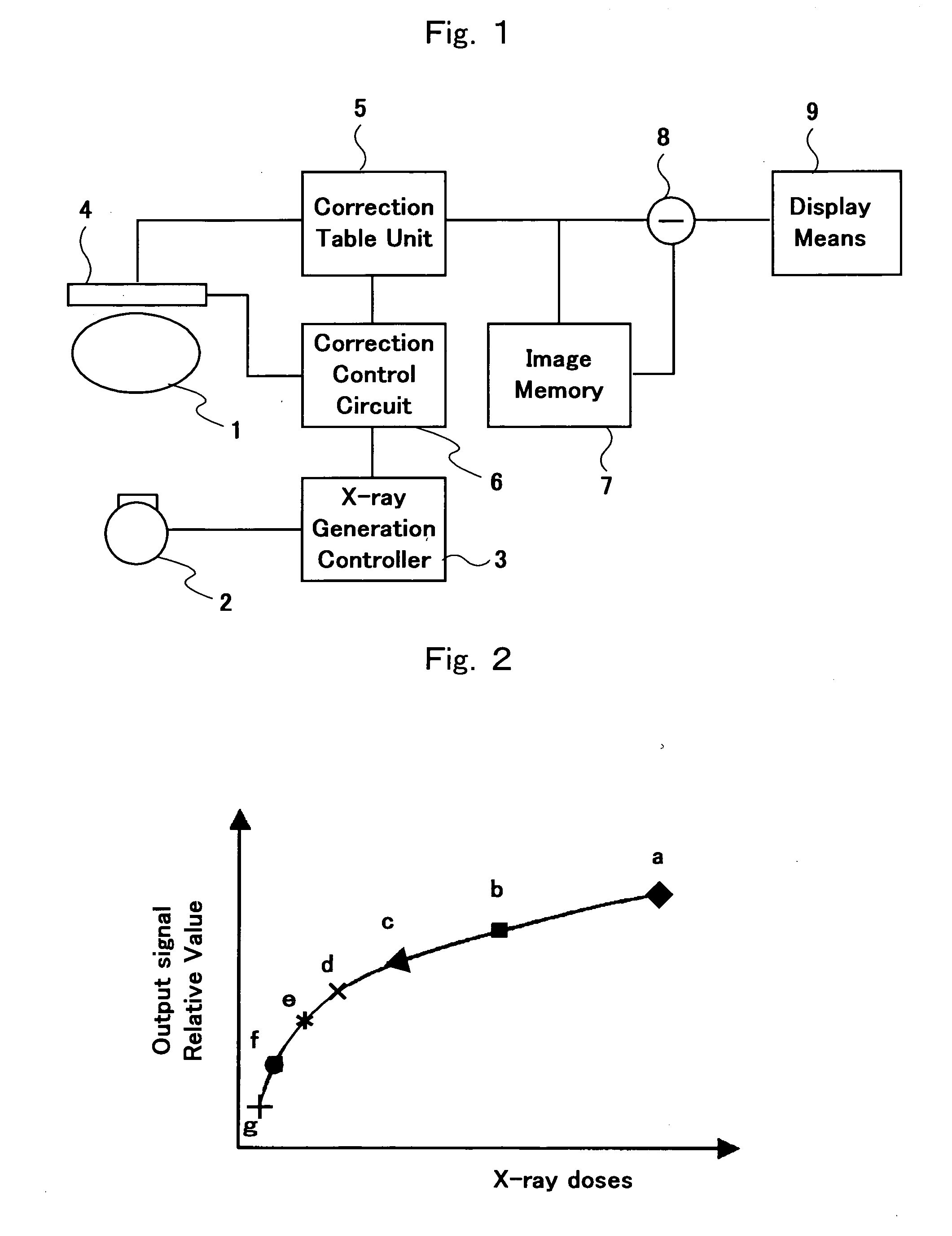
[0019]FIG. 1 is a block diagram showing an outline structure representing an embodiment of an X-ray diagnosis apparatus with an X ray flat panel detector according to the present invention.

[0020] As shown in FIG. 1, the X-ray diagnosis apparatus according to the present embodiment is provided with an X ray source 2 which irradiates X ray to an object 1, an X ray generation controller 3 which controls the irradiation of X ray from the X ray source 2 to the subject 1, an X ray flat panel detector 4 which detects X ray transmitted through the subject 1 and outputs as an image signal, a correction table 5 having a plurality of correction tables which correspond to the output order of image data representing the image signals successively output from the X ray flat panel detector 4, a correction control circuit 6 which controls the X ray generation controller 3 and the X ray flat pa...


PUM

PropertyMeasurementUnit
areaaaaaaaaaaa
time intervalaaaaaaaaaa
heightaaaaaaaaaa

Abstract

A correction table unit (5) contains correction tables for correcting output values of image data of the first image, the second image, . . . , the n-th image successively output from an X-ray plane detector (4) of a radiographic image diagnosis device and having different output rise characteristics. After correction of the image data, the second image data is subtracted from the first image data, . . . , and the n-th image data is subtracted from the first image data by a subtraction unit (8). As a result, a subtraction image, i.e., an angiographic image is displayed on display means (9). Since the affect of the different rise characteristics of each image data is eliminated, it is possible to obtain an angiographic image having a uniform background brightness and a preferable contrast.

Description

FIELD OF THE INVENTION [0001] The present invention relates to an X-ray diagnosis apparatus having an X ray flat panel detector and in particular, relates to an X-ray diagnosis apparatus which is provided with a function of correcting a low output characteristic at an initial stage of image taking by an X ray flat panel detector. BACKGROUND ART [0002] These days X-ray diagnosis apparatuses use as their X ray detectors an X ray flat panel detector. The X ray flat panel detector is constituted by a scintillator (for example, made of cesium iodide (CsI)) which converts X ray transmitted through an object to be examined into light, photodiodes (for example, made by amorphous silicon (a-Si)) which converts the light output from the scintillator into electric charge and switching elements such as, for example, thin film transistors (TFT) which read the electric charge, and, for example, has an active area of 30×40 cm2 and 7,400,000 pixels. [0003] However, as referred to, for example, in R...

Claims


Application Information

Patent Timeline
Patent Type & Authority Applications(United States)
IPC IPC(8): A61B6/00H04N5/32
CPCA61B6/481H04N5/3205A61B6/504
Inventor SUZUKI, KATSUMI
Owner HITACHI MEDICAL CORP
Why Eureka
Try Eureka