Compact compressors and refrigeration systems

Inactive Publication Date: 2005-06-09
TECUMSEH PROD CO
View PDF60 Cites 20 Cited by
  • Summary
  • Abstract
  • Description
  • Claims
  • Application Information

AI Technical Summary

Benefits of technology

[0016] In a further form thereof, the present invention provides a compact refrigeration system, including a first housing component having a simple geometry profile including an exterior wall, and a groove formed within the exterior wall; a second housing component into which the first housing component is

Problems solved by technology

Also, as electronic equipment has become increasingly smaller, the heat dissipation requirements of such equipme

Method used


Image

  • Compact compressors and refrigeration systems
  • Compact compressors and refrigeration systems
  • Compact compressors and refrigeration systems

Examples


first embodiment

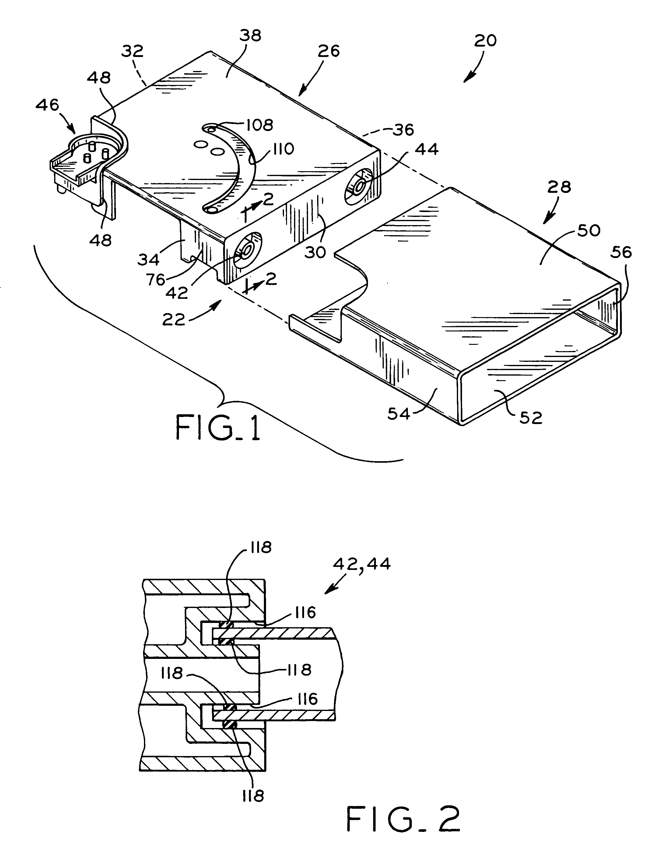
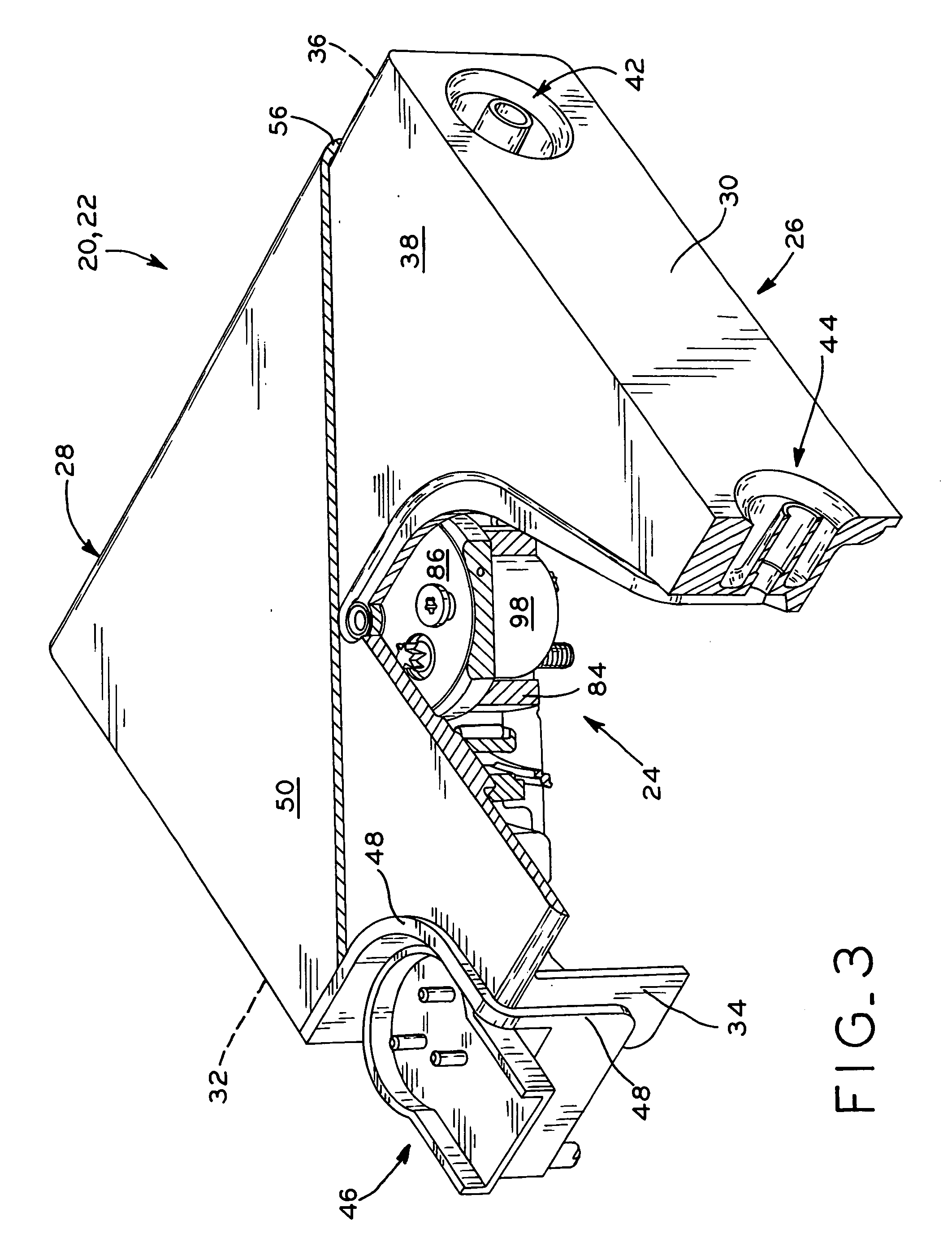
[0034] The present invention provides both compact compressors and compact refrigeration systems which, in the exemplary application described below, may be used to provide cooling to electronic equipment. A compact compressor 20 according to the present invention is shown in FIGS. 1-8. With initial reference to FIGS. 1-4, compressor 20 generally includes a hermetic enclosure or housing 22 and a motor-compressor unit 24 disposed within hermetic housing 22. Referring to FIG. 1, housing 22 generally includes a first or inner housing component 26 and a second or outer housing component 28. To assemble compact compressor 20, first housing component 26 is insertable within second housing component 28, and the foregoing are secured to one another such as by welding in the manner described below.

[0035] As shown in FIGS. 1 and 3, compressor housing 22 has a simple geometry profile, shown herein as a rectilinear profile. In this manner, compact compressor 20 may be inserted into a slot in an...

second embodiment

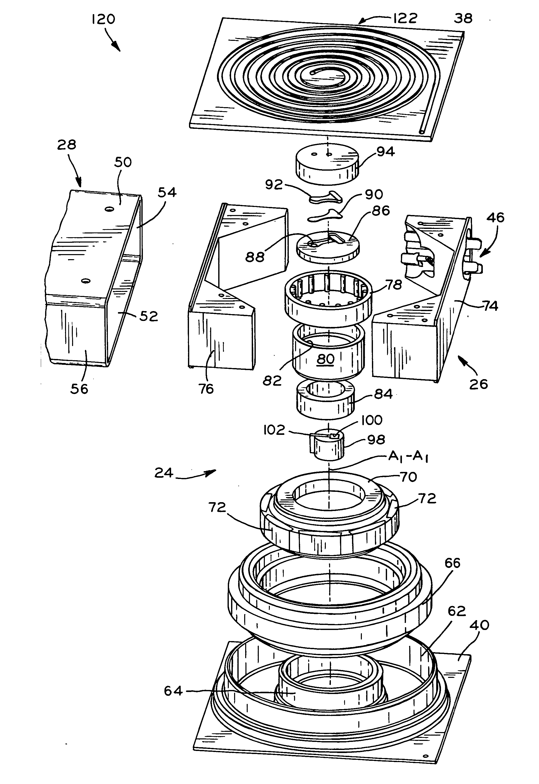
[0048] A compact refrigeration system (“CRS”) 120 according to the present invention is shown in FIGS. 7-13. Except as described below, CRS 120 includes a housing22 with a compact motor-compressor unit 24 which is substantially identical to that of compact compressor 20 described above, and the same reference numerals will be used below to designate identical or substantially identical features between compact compressor 20 and CRS 120. Housing 22 of CRS 120, similar to that of compact compressor 20, is both compact and modular to facilitate its use in changing environments and smaller spaces associated with electronic equipment. As described below, housing 22 of CRS 120 includes a compact compressor mechanism 60 substantially identical to that described above with respect to compact compressor 20, and additionally includes other refrigeration system components, including a condenser, expansion device, and evaporator, which are located within housing 22 to hermetically seal CRS 120 ...


PUM


Abstract

Compact compressors and refrigeration systems that can be used to cool computers, servers, and other electronic equipment. Each compact compressor or refrigeration system includes a compact, substantially enclosed hermitic housing having a simple geometry profile, such as a rectilinear profile, which enables the compact compressor or refrigeration system to be easily inserted within a slot, for example, of an electronic component such as a computer server. In one embodiment, a compact compressor is provided, which includes a motor-compressor unit within the housing, including a stator, a rotor disposed interiorly of the stator, and a compressor mechanism disposed interiorly of the rotor to provide a compact profile. In another embodiment, the housing includes the foregoing compact motor-compressor unit, and further includes a condenser formed within one of the walls of the housing and an evaporator formed within another wall of the housing such that the housing defines a completely contained, compact refrigeration system. Alternatively, in another embodiment, the housing may include only one of the condenser and evaporator, with the other of the condenser and evaporator configured as a modular component which is attached to the housing.

Description

CROSS REFERENCE TO RELATED APPLICATIONS [0001] This application claims the benefit under 35 U.S.C. § 119(e) of U.S. Provisional Patent Application Ser. No. 60 / 527,798, entitled COMPACT REFRIGERATION SYSTEMS AND HEAT EXCHANGERS, filed on Dec. 8, 2003, assigned to the assignee of the present patent application, the disclosure of which is expressly incorporated herein by reference.BACKGROUND OF THE INVENTION [0002] 1. Field of the Invention [0003] The present invention relates to compact, modular cooling systems, and in particular, to compact compressors and refrigeration systems for electronic equipment cooling. [0004] 2. Description of the Related Art [0005] Conventional refrigeration systems are typically semi-permanent or permanent systems. For example, in a typical refrigerator, it is not necessary to be able to independently move the refrigeration components with respect to the rest of the refrigerator and the components of such refrigeration systems are permanently installed in ...

Claims


Application Information

Patent Timeline
IPC IPC(8): F04C18/344F04C23/00F04C29/00F25B1/00F25B1/04F25B31/00G06F1/20
CPCF04C18/3442F04C23/00G06F1/20F25B1/00F25B2500/01F04C2210/26
Inventor MANOLE, DAN M.COFFEY, DONALD L.FROSTICK, ALICIA
Owner TECUMSEH PROD CO
Why Eureka
Try Eureka