Radio communication apparatus and common control channel reception method

Inactive Publication Date: 2005-06-09
MITSUBISHI ELECTRIC CORP
View PDF10 Cites 22 Cited by
  • Summary
  • Abstract
  • Description
  • Claims
  • Application Information

AI Technical Summary

Benefits of technology

[0010] This configuration makes it possible to receive the response message contained in the common control channel positively even in a handover area in which the cell switching can occur frequently, thereby enabling the improvement of the stability of the communication.
[0020] This makes it possible to receive the response message contained in the common control channel positively even in a handover area in which the cell switching can occur frequently, thereby enabling the improvement of the stability of the communication.

Problems solved by technology

As for the response to the request message such as the reconnection request message from the network side, it can sometimes be transmitted with a large delay because of the processing load of the network.
Repetition of such operation will bring about a timeout because a predetermined time period has elapsed without receiving any response to the request message, thereby causing a communication problem such as call disconnection.
Thus, the conventional mobile station rather easily cause a communication problem such as a call disconnection if the response to the request message via the common control channel is delayed because of the processing delay on the network side, thereby offering a problem of bringing about unstable communication.

Method used


Image

  • Radio communication apparatus and common control channel reception method
  • Radio communication apparatus and common control channel reception method
  • Radio communication apparatus and common control channel reception method

Examples


embodiment 1

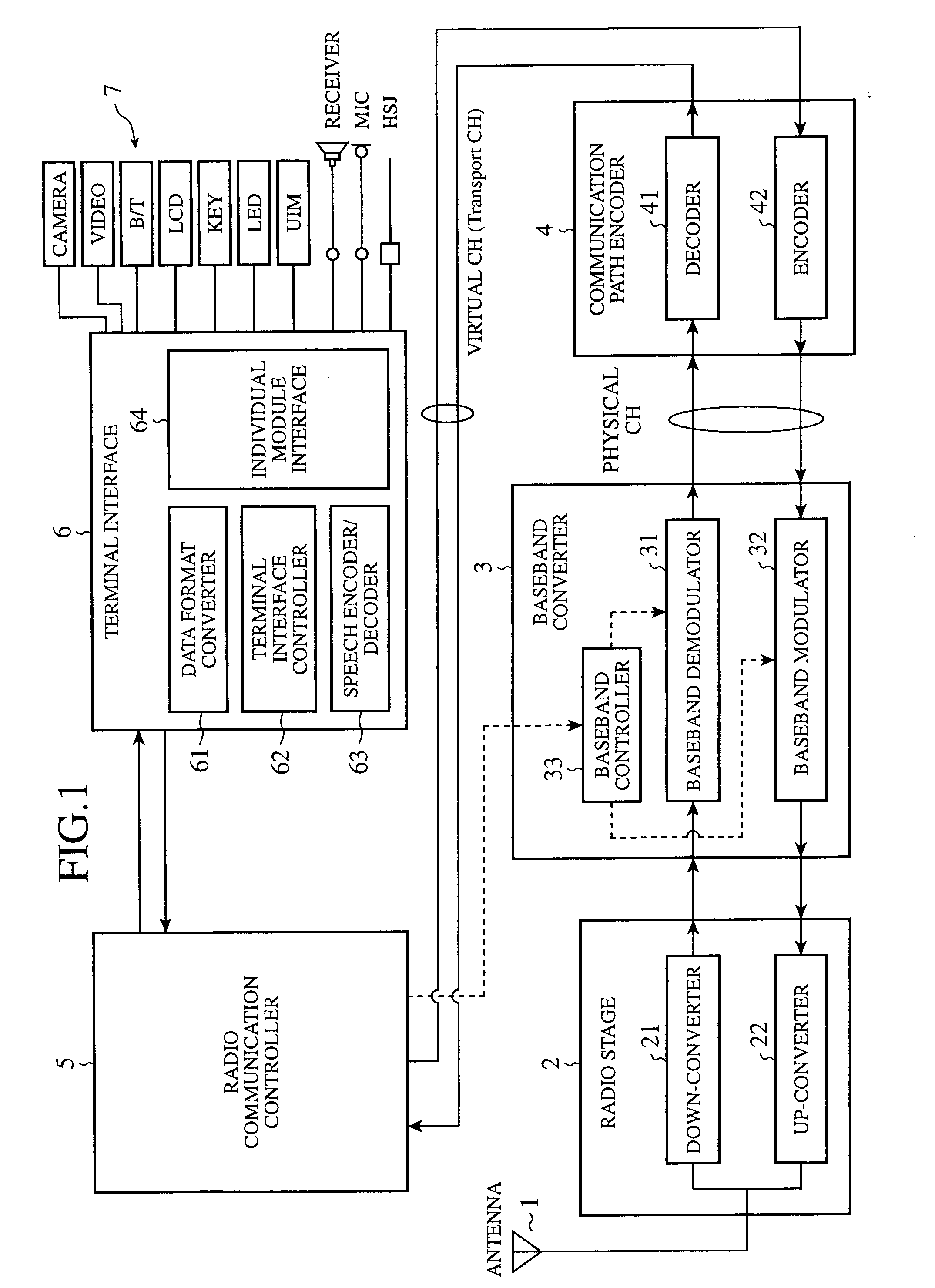
[0032] The embodiment 1 in accordance with the present invention will be described. FIG. 1 is a functional block diagram showing a radio communication apparatus (mobile station) of the embodiment 1 in accordance with the present invention. In FIG. 1, the reference numeral 1 designates an antenna for transmitting and receiving a high frequency signal to and from the base station; and 2 designates a radio stage including a down-converter 21 and an up-converter 22. The down-converter 21 down-converts the high frequency signal received from the base station, and outputs a digital signal. The up-converter 22 up-converts a modulated digital signal to a high frequency band.

[0033] The reference numeral 3 designates a baseband modulator-demodulator including a baseband demodulator 31 for carrying out baseband demodulation, a baseband modulator 32 for carrying out baseband modulation, and a baseband controller 33 for controlling them in accordance with the control from a radio communication ...

embodiment 2

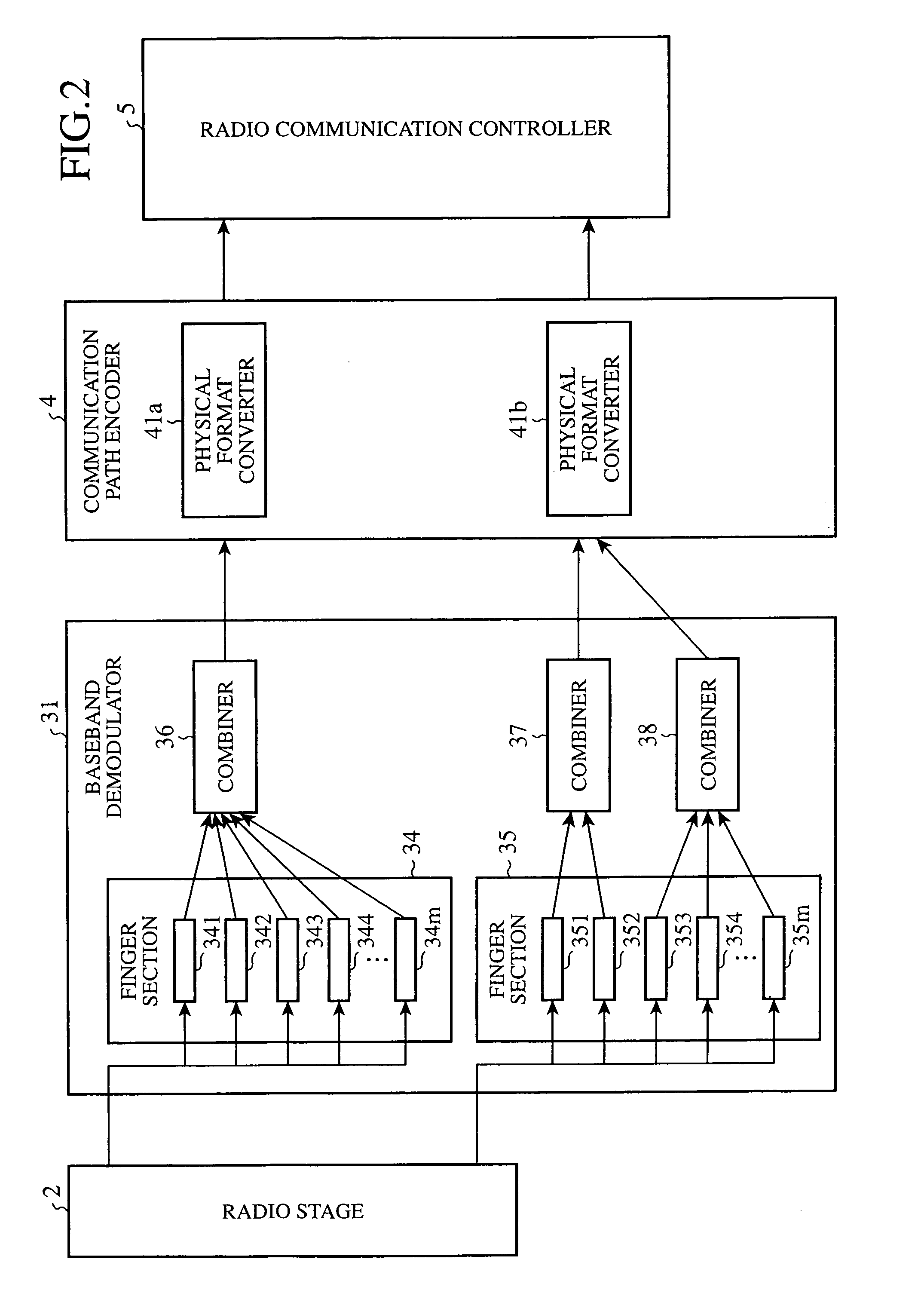
[0055] Next, an embodiment 2 in accordance with the present invention will be described. The functional block diagram of the radio communication apparatus (mobile station) of the present embodiment 2 is the same as that of FIG. 1. Referring to FIG. 8, a detailed arrangement of the baseband demodulator 31 with a characteristic configuration will be described. In FIG. 8, the same reference numerals designate the same components as those of FIG. 2. The baseband demodulator 31 includes the finger sections 34 and 35 each for despreading the digital signal fed from the radio stage 2 for each receiving path from the base station, and combiners 36 and 39 for rake combining the signals despread for respective receiving paths. The finger sections 34 and 35 include a plurality of fingers 341, 342, . . . , 34m and 351, 352, . . . , 35n provided for the individual receiving paths, where m and n are integers. The finger section 34 and combiner 36 are used for demodulating the physical channel (PC...


PUM


Abstract

A radio communication apparatus includes: a transmitting section for transmitting a request message to a first cell and a second cell; a first combiner for demodulating a first common control channel transmitted from the first cell; a second combiner for demodulating a second common control channel transmitted from the second cell; a baseband controller for starting the first and second combiners, and for controlling the combiners into a state in which the combiners can demodulate the first and second common control channels simultaneously; and a radio communication controller for receiving a response message to the request message contained in one of the first and second common control channels. The radio communication apparatus can receive the response message contained in the common control channels positively even in a handover area where cell switching can occur frequently, and can improve the stability of the communication.

Description

TECHNICAL FIELD [0001] The present invention relates to a mobile station in a CDMA communication system, and more particularly to a receiving method of a common control channel in a handover area. BACKGROUND ART [0002] A conventional mobile station (radio communication apparatus) receives a physical channel SCCPCH, a common control channel a base station transmits, via a single radio link (Radio Link, RL), as specified by Max no of S-CCPCH RL (=1) described in 3GPP (3rd Generation Partnership Project) TS25.331 10.3.3.27 Physical channel capability. FIG. 9 is a block diagram showing a receiving section of such a mobile station. [0003] In FIG. 9, the reference numeral 101 designates a radio stage for receiving a high frequency signal from a base station, and for converting it to a digital signal; and 102 designates a baseband demodulator for demodulating the digital signal from the radio stage 101. The base band demodulator 102 includes finger sections 103 and 104 each for despreading...

Claims


Application Information

Patent Timeline
IPC IPC(8): H04W36/08H04W36/18H04W88/02H04W88/06
CPCH04W36/18H04W88/06H04W88/02
Inventor KUBO, YOSHIHIRO
Owner MITSUBISHI ELECTRIC CORP
Why Eureka
Try Eureka