
Apparatus and method for controlling vehicle

a technology of apparatus and vehicle, applied in the direction of electric control, machines/engines, instruments, etc., can solve the problems of power generation being stopped during the stop of engine operation, and it is difficult to start the next engine operation, so as to achieve the effect of suppressing battery was

Inactive Publication Date: 2005-06-09
HITACHI LTD
View PDF4 Cites 13 Cited by
  • Summary
  • Abstract
  • Description
  • Claims
  • Application Information

AI Technical Summary

Benefits of technology

[0007] The present invention has an object to suppress the battery waste during an engine operation is stopped, in a system for controlling the leakage diagnosis or the like after a standby time has elapsed after the engine operation was stopped.

Problems solved by technology

However, the power generation is stopped during the stop of engine operation.
Therefore, if a standby time until the start of the leakage diagnosis is made longer, a battery is wasted due to the power consumption by a control unit during the standby time, and consequently, it becomes hard to start the next engine operation.

Method used


Image

  • Apparatus and method for controlling vehicle
  • Apparatus and method for controlling vehicle
  • Apparatus and method for controlling vehicle

Examples


Embodiment Construction

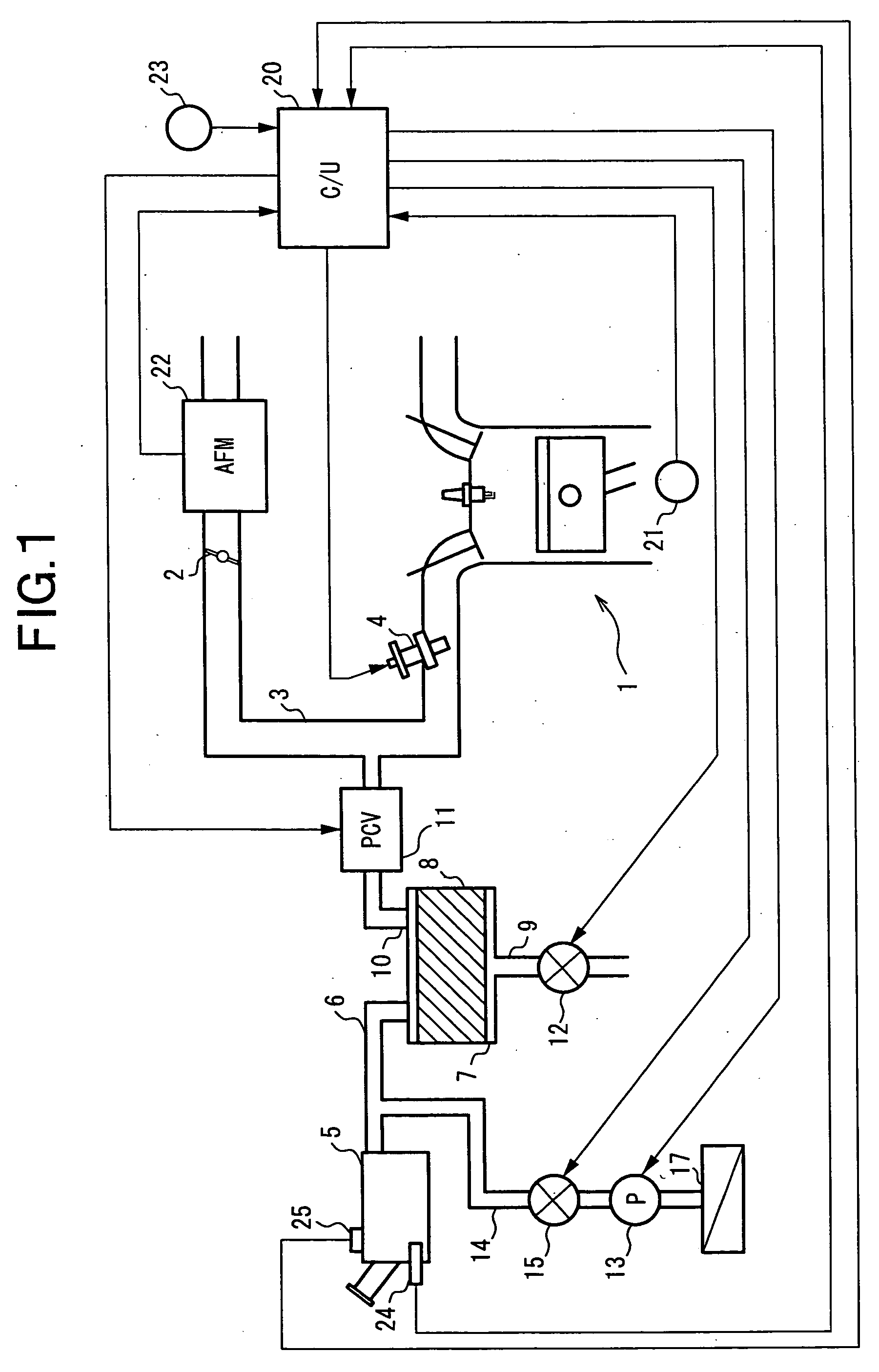
[0016]FIG. 1 shows a system configuration of an internal combustion engine in an embodiment.

[0017] In FIG. 1, an internal combustion engine 1 is a gasoline engine installed in a vehicle (not shown in the figure).

[0018] A throttle valve 2 is disposed in an intake pipe 3 of internal combustion engine 1.

[0019] For each cylinder, a fuel injection valve 4 is disposed on the downstream side of throttle valve 2.

[0020] Fuel injection valve 4 is opened based on an injection pulse signal output from a control unit 20.

[0021] Internal combustion engine 1 is provided with a fuel vapor processing apparatus.

[0022] The fuel vapor processing apparatus is for adsorbing and trapping the fuel vapor generated in a fuel tank 5 to a canister 7 via a fuel vapor inlet passage 6, and for supplying to internal combustion engine 1 the fuel vapor adsorbed and trapped to canister 7, to be burned.

[0023] Canister 7 is a container filled with the adsorbent 8 such as activated carbon.

[0024] Further, a new ai...


PUM


Abstract

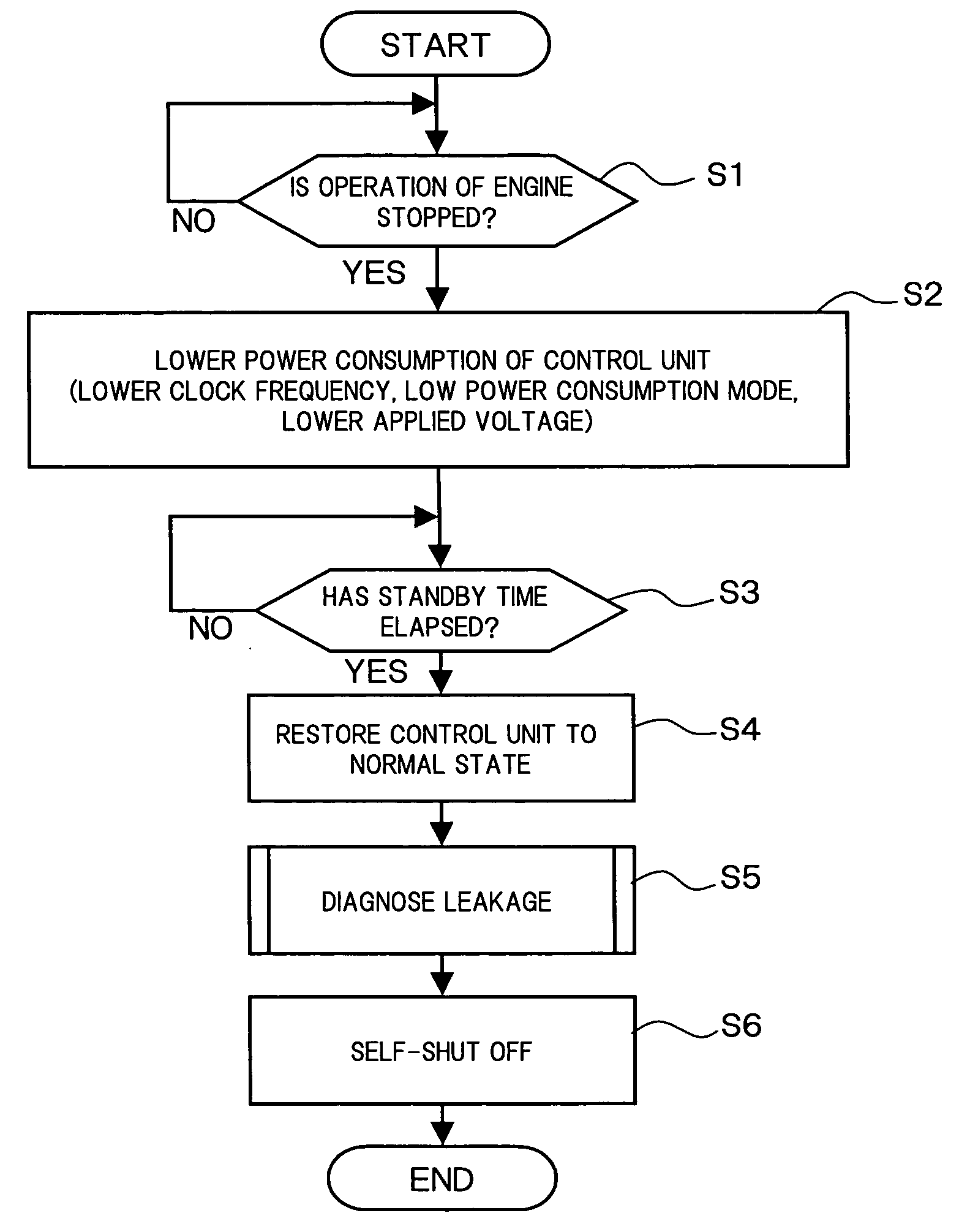
When an operation of internal combustion engine is stopped, the power consumption of a control unit is lowered, to measure an elapsed time. When the elapsed time reaches a standby time, the processing of lowering the power consumption is cancelled, to diagnose whether or not the leakage occurs in an evaporation purge line of a fuel vapor processing apparatus.

Description

FIELD OF THE INVENTION [0001] The present invention relates to an apparatus and a method for controlling a vehicle, and in particular, to a control apparatus and a control method for performing a previously determined control after a standby time has elapsed from an engine operation was stopped. RELATED ART [0002] Japanese Unexamined Patent Publication No. 2003-013810 discloses a diagnosis apparatus for diagnosing whether or not the leakage occurs in an evaporation purge line of a fuel vapor processing apparatus. [0003] In this diagnosis apparatus, the evaporation purge line is shielded after an engine operation has been stopped, and it is diagnosed whether or not the leakage occurs in the evaporation purge line, based on a driving load of an air pump at the time when the air pump supplies air to the evaporation purge line. [0004] If the fuel vapor is generated when the evaporation purge line is being pressurized, since a pressure in the evaporation purge line is changed by an influ...

Claims


Application Information

Patent Timeline
Patent Type & Authority Applications(United States)
IPC IPC(8): F02D41/04F02D41/26F02M25/08
CPCF02D41/042F02M25/0827F02D41/26
Inventor HOSOYA, HAJIMEWAKAIRO, MASAHIKO
Owner HITACHI LTD
Learn More