Method for forming footwear structures using thermoforming

a technology of thermoforming and footwear, applied in the field of footwear structures and manufacturing methods, can solve the problems of difficult to precisely define the terms sole and midsole, high mold cost, operating cost,

Inactive Publication Date: 2005-06-16
POLYWORKS
View PDF77 Cites 87 Cited by
  • Summary
  • Abstract
  • Description
  • Claims
  • Application Information

AI Technical Summary

Benefits of technology

[0015] It is an object of the present invention to avoid or reduce at least some of the above problems and/or restrictions by providing a method and apparatus for forming footwear structures by using a single sheet thermoforming process. Single sheet th

Problems solved by technology

It can be difficult to precisely define the terms sole and midsole, because the terms are not always used uniformly, and the same or similar components could be considered as part of a sole or as part of a midsole.
In addition to operating costs, mold costs are very high due to dual-mold requirements, heat dissipation, and high-cost mold materials.
For durability reasons, molds used in twin-sheet processing must be made of steel, which is relatively expensive to cut and is difficult to handle.
Also, cycle times using a two-mold, twin-sheet process are typically between 60 and 90 seconds, which is not conducive to mass production.
Further, the cost-per-unit is often prohibitively high due to the significant costs of multiple materials, the combining/assembly process and associated labor, and the costs associated with defects.
Further, with respect to the foam-backing process, molded uppers made using this method are relatively heavy, due to the combination of materials used.
In addition, the molded uppers cannot be made breathable by the above-described process itself; additional processes are required to create apertures in the molded uppers for this purpose.
Such additional processes are expensive, time-co

Method used


Image

  • Method for forming footwear structures using thermoforming
  • Method for forming footwear structures using thermoforming
  • Method for forming footwear structures using thermoforming

Examples


Embodiment Construction

[0039] Referring now to the drawings, where like reference numeral designations identify the same or corresponding parts throughout the several views, several embodiments of the present invention will now be described.

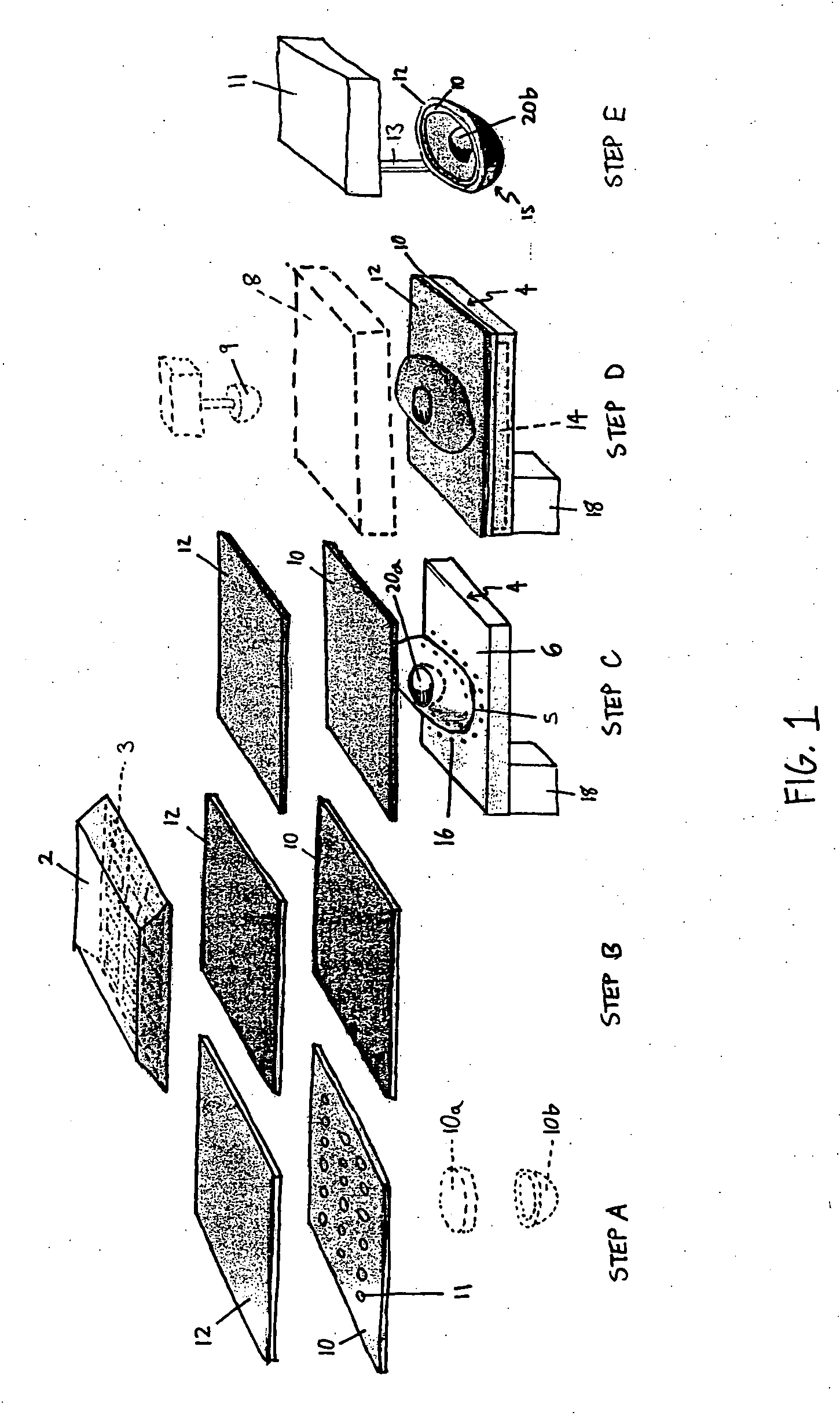
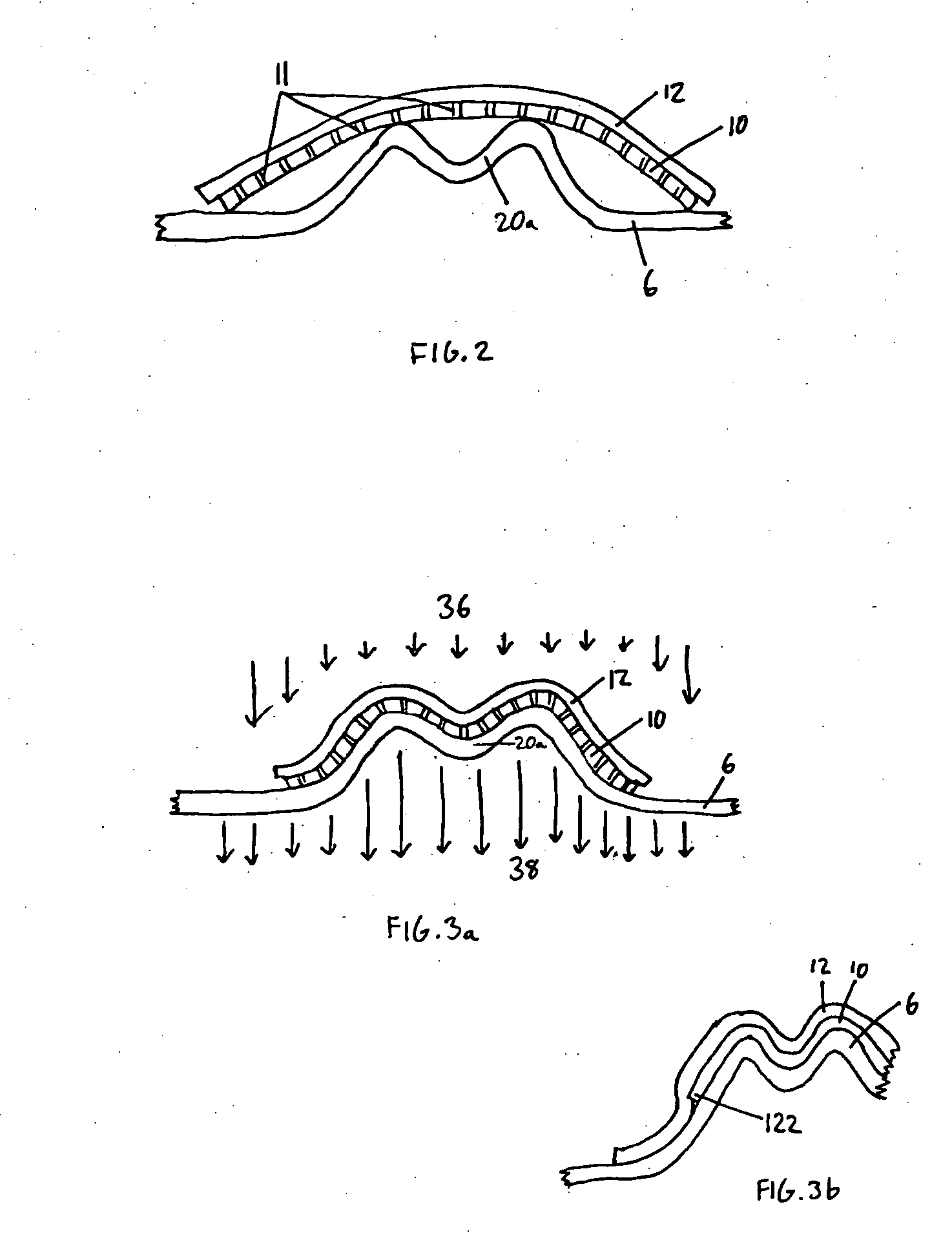
[0040] In accordance with a preferred method of manufacturing a footwear structure, such as an upper or a sole assembly, a single-sheet, single-face mold, thermoforming process is used to create a complete footwear structure. In this way, many of the shortcomings associated with the above-described known processes can be avoided. For example, using the preferred method, the need to create a mating half-component on an additional mold, as required in twin-sheet processing, is eliminated. Also, the process of single-sheet thermoforming can be used to create a composite sheet in the form of a footwear structure from two or more material layers using only a single forming surface, a concept that is novel to the present invention. Further, a typical cycle time for a single...


PUM


Abstract

Footwear and footwear structures are provided as well as methods for forming composite components for footwear or footwear structures. In forming the structures, two material layers are overlaid such that the two material layers are in contact with one another. The two material layers are heated to a forming temperature and are then vacuum-formed together to form a composite material layer in a three-dimensional form of the footwear structure. A provided footwear structure includes an upper and a sole assembly attached to the upper. The sole assembly includes a first material layer made of a thermoplastic, and a second material layer attached to the first material layer. The first material layer includes a recessed area including a flat support portion, and is transparent or translucent. The second material layer includes a portion that is positioned on a surface of the recessed area, and a color of the second material layer indicates a location and/or a function of the second material layer.

Description

BACKGROUND OF THE INVENTION [0001] 1. Field of the Invention [0002] The present invention generally relates to footwear, more particularly, to footwear structures and manufacturing methods for forming footwear structures by thermoforming one or more layers of material. [0003] 2. Discussion of the Background [0004] A typical athletic shoe includes an upper, a midsole, and an outsole. The upper covers and protects the instep, heel, and side portions of the foot and is commonly constructed of leather or other natural or synthetic materials (e.g., nylon). The particular sport for which the athletic shoe is to be utilized often dictates the material or materials used to construct the upper. For example, for the upper of a basketball shoe, it is often desirable to utilize a heavy material such as leather because leather provides more support to the wearer's foot and ankle than canvas or nylon. A running shoe upper, however, might be formed almost entirely of a synthetic material because s...

Claims


Application Information

Patent Timeline
IPC IPC(8): A43B13/18B29D35/12
CPCA43B13/181B29D35/122A43B23/026A43B23/024A43B23/0255A43B23/0235
Inventor SKAJA, JOSEPHLIU, KENNETH J.PRESKAR, DAVID JOSEPHNICHOLS, STEVEN B.
Owner POLYWORKS
Why Eureka
Try Eureka