Deployable truss having second order augmentation

a truss and second-order technology, applied in the field of deployable truss structures, can solve the problems of thermal induced bending, distortion, and limited utility of stems, and achieve the effects of reducing the free buckling length of individual strut members, increasing the moment of inertia, and buckling strength

Active Publication Date: 2005-06-16
NORTHROP GRUMMAN SYST CORP
View PDF99 Cites 68 Cited by
  • Summary
  • Abstract
  • Description
  • Claims
  • Application Information

AI Technical Summary

Benefits of technology

[0027] For added rigidity, strut members of a column assembly may be connected to each other between the first and second ends using, for example, a rigidizable resin, a fixed spacer, or a deployable spacer. Connecting strut members between the ends of a column assembly provides mutual bracing to the strut members and decreases the free buckling length of the individual strut members. Spacers may be used to radially space the strut members away from the longitudinal centerline of a column assembly to increase its moment of inertia, and hence its buckling strength.
[0028] Moreover, graphite fiber elements manufactured from high modulus fibers with axial or near-axial alignment can be used as strut members in the column assemblies of the deployable trusses according to the present invention. Use of such elements will maximize structural efficiency and thermal stability of the deployable truss.
[0030] In one embodiment of the present invention, an articulated deployable boom truss is provided. Augmenting a deployable articulated lattice boom with column assemblies of the present invention permits the continued use of reliable heritage kinematic solutions during the deployment of the augmented boom. Articulated boom trusses of the present invention provide structural determinacy during deployment comparable to heritage systems. Additionally, graphite fiber construction can be optimally employed in the articulated boom systems of the present invention for even greater improvements in mass efficiency, stowage volume, and / or thermal stability over heritage articulated boom truss systems.

Problems solved by technology

However, STEMs have strength limitations since the deployed metal strip does not form a closed section.
STEMs are also limited in utility due to susceptibility to thermally induced bending.
Such inconsistent heating could cause the side of the STEM receiving the solar radiation to expand more than the shielded side of the STEM, resulting in thermal induced bending, and distortion, of the STEM.
Distortions in booms are generally undesirable and, in particular, distortions can reduce axial load capability.
In practice, therefore, the ratio of the length to diameter of a boom is generally kept below the point where factors such as manufacturing straightness errors, thermal bending, and unintended minor load eccentricities leave the boom susceptible to collapse by buckling.
However, using a boom comprised of a simple thin-walled cylinder will not be mass optimized, if the required wall thickness of the boom is greater than the optimal wall thickness required to meet stiffness requirements.
This situation occurs when the optimal wall thickness required to meet stiffness concerns is so thin that the boom wall would have unreliable strength properties due to small manufacturing imperfections in the boom wall.
Such imperfections are difficult to avoid and to predict.
In addition, as optimum wall thickness decreases, such imperfections are more likely to initiate failure by local wall buckling from loads well below the bulk properties of the material being used to fabricate the boom.
This limits the usefulness of thin-walled tubular shell booms, such as STEMs, and is one impetus for using a range of lattice type boom structures in space applications.
Joint design is also important to performance of articulated truss structures since joints typically carry risks of reliability, increase the mass of the structure, and limit compaction.
As a result, in typical performance regimes, current coilable truss designs possess far in excess of a desirable amount of stowed strain energy, resulting in excessive push forces.
The required additional mass of the deployment mechanism to safely handle the push force of current coilable trusses adds parasitic mass and limits their overall mass efficiency.
But graphite fiber composite materials have limited applicability in known coilable lattice structures because graphite fiber composite materials have strain capabilities typically two to three times lower than glass fiber composite materials.
Therefore, only much smaller, and hence weaker, longer rods can withstand the curvature encountered during stowage.
This limits the utility of graphite composite longerons in currently practiced coilable lattice structure because the maximum diameter graphite longeron (approximately ⅓ that of an S2 glass fiber longeron) that can be used in known coilable structures would possess up to approximately 80 times less inertia.
But, as always, the stacking of individual longeron elements restricts compaction capability because slenderness limits constrain the minimum realistic diameter of the longeron elements.
But, in practice, it has been difficult to achieve the structural efficiency of an articulated structure with an inflatable system due to mass overhead in non-structural systems such as: bladder materials, thermal barrier layers, node fittings, and inflation equipment and sequencing mechanisms.
Inflatable systems are also plagued with structural inefficiencies inherent with the use of folding or rolling collapsed composite tubes.
To allow the folding or rolling of collapsed composite tubes, the graphite material must be capable of withstanding high strain, requiring a reduction in fiber stiffness, fiber to matrix volume ratios, and / or the use of a woven fabric, which reduces the effective stiffness.
However, such systems are not generally collapsible, although some have been proposed.
The mass efficiency of this system is high and the structure is stable, but the compaction ratio is poor.
Allowing the tubes to be partially flattened, as described in U.S. Pat. No. 6,343,442 to Marks, increases the compaction, but it is still not satisfactory.
Inflatables, folded, and flattened lattice structures do not have precise kinematics and suffer from reduced stiffness and strength during deployment.

Method used


Image

  • Deployable truss having second order augmentation
  • Deployable truss having second order augmentation
  • Deployable truss having second order augmentation

Examples


Embodiment Construction

[0050] The preferred embodiments of the invention will now be described with reference to the drawings. To facilitate description, reference numerals designating an element in one figure will represent the same element in any other figure.

[0051] Historically, lattice boom trusses have been more effective than simple beams consisting of a rod or tube in lightly loaded space deployable applications. The present invention further improves key performance metrics of lightly loaded deployable trusses for use in space by employing secondary augmentation.

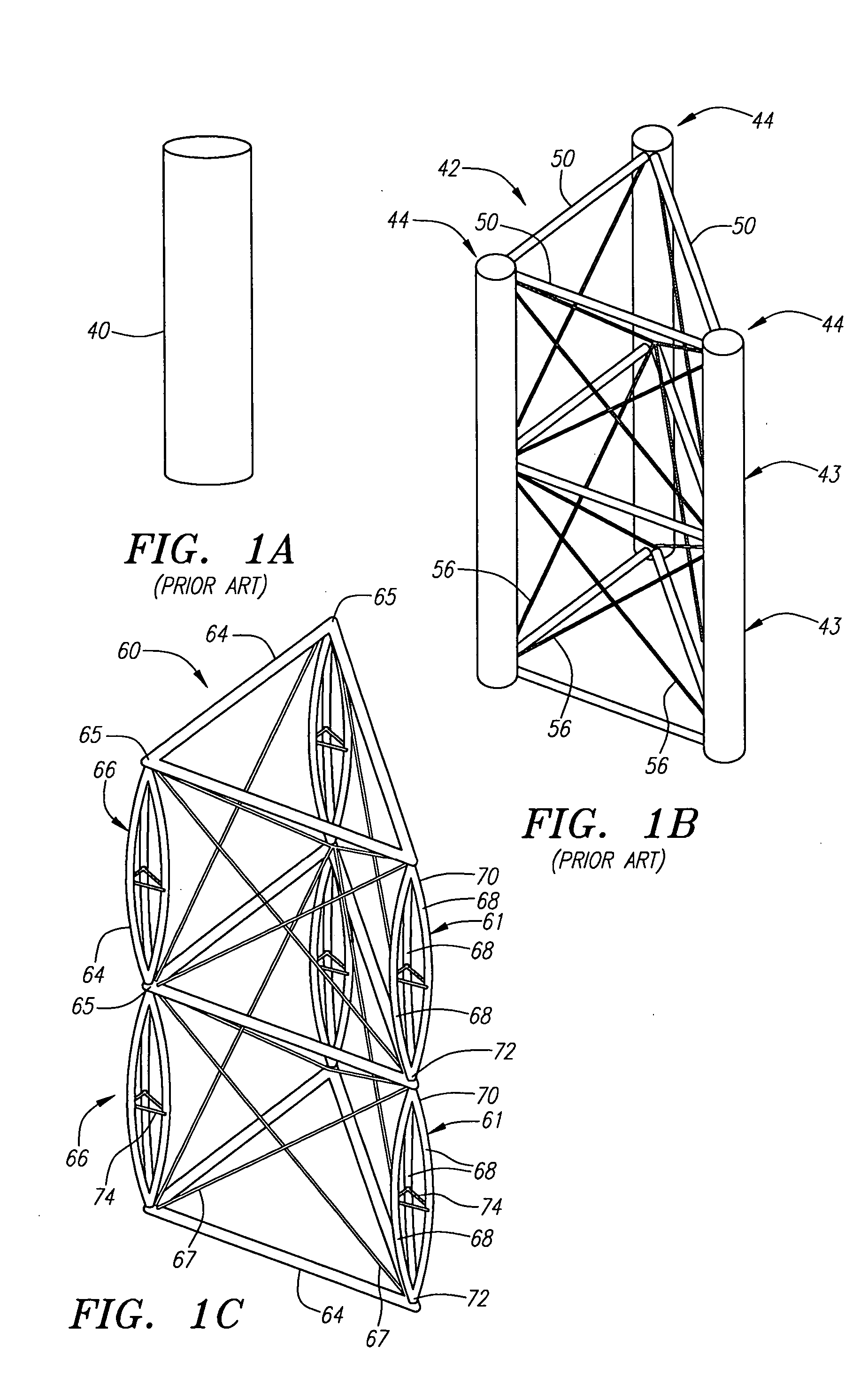
[0052]FIGS. 1A-1D schematically illustrate boom structures exhibiting increasing structural hierarchy. FIG. 1A shows a portion of a boom 40 made from a single solid rod. This is referred to as a 0th-order structure since there is no latticing structure whatsoever.

[0053]FIG. 1B illustrates a portion of a typical prior art lattice boom truss 42. Boom truss 42 comprises three longerons or columns 44. The aggregate area of the three columns...


PUM


Abstract

A deployable truss is formed from a plurality of column members connected at their ends where at least some of the column members are formed from column assemblies, each including a plurality of strut members that are at least connected to each other at a first and second end of the column assembly. For added rigidity, strut members of a column assembly may be connected to each other between the first and second ends using, for example, a rigidizable resin, a fixed spacer, or a deployable spacer. Connecting strut members between the ends of the column assembly provides mutual bracing to the strut members and decreases the free buckling length of the individual strut members. Spacers are preferably configured to radially space the strut members away from the longitudinal centerline of the column assembly to increase its moment of inertia, and hence its buckling strength.

Description

FIELD OF THE INVENTION [0001] The present invention relates to the field of extendible truss structures, and more particularly to lightweight deployable truss structures used in space applications. BACKGROUND OF THE INVENTION [0002] Deployable structures made for use in space have generally been linearly deployed systems extended from a fixed base. These structures are commonly referred to as booms and can be divided into two categories: shell and lattice booms. Successful designs share traits of mass efficiency, low packaged volume, and reliability. [0003] One specific type of a shell boom, referred to as a STEM in the space industry, for Storable Tubular Extendable Member, is disclosed in U.S. Pat. No. 3,144,104. A STEM, which typically incorporates a coilable thin metal strip, such as shown in the figures of U.S. Pat. No. 3,144,104, are precurved and form a cylindrical shell when deploying. These devices have found use in low load applications such as antennas and gravity gradien...

Claims


Application Information

Patent Timeline
Patent Type & Authority Applications(United States)
IPC IPC(8): B64G1/22B64G99/00E04C3/00E04H12/10H01Q1/08H01Q1/12
CPCB64G1/222B64G9/00H01Q1/1235E04H12/10H01Q1/08E04C3/005B64G99/00
Inventor MURPHY, DAVID M.MURPHEY, THOMAS W.MCEACHEN, MICHAEL E.BOTKE, MATTHEW M.
Owner NORTHROP GRUMMAN SYST CORP
Why Eureka
Try Eureka