Spindle or worm drive for adjustment devices in motor vehicles

a technology of motor vehicles and worm drives, which is applied in the direction of movable seats, roofs, gearing, etc., can solve the problems of vehicle seats connected to the adjusting rail moving uncontrollably

Active Publication Date: 2005-06-16
BROSE FAHRZEUGTEILE GMBH & CO KG
View PDF5 Cites 37 Cited by
  • Summary
  • Abstract
  • Description
  • Claims
  • Application Information

AI Technical Summary

Benefits of technology

[0008] The solution according to the invention provides a play-free bearing of the gearing elements protected against dirt as well as a crash-safe support of the gearing mechanism and thus of the relatively movable parts of the adjustment device as well as a pivotal action of the gearing mechanism for connecting adjustment parts which are able to pivot about an axis.
[0009] The solution according to the invention is based on the idea of arranging the gear elements in a gear housing surrounding the gear elements in the form of a capsule protected against dirt and damage and of arranging the gear housing in turn free from backlash and where necessary able to pivot about at least one axis in a bearing shell which is designed and intended to take up the crash forces and thus to ensure a crash-safe support of the gear mechanism so that the relatively movable parts of the adjustment device also remain connected together even in the event of a crash.
[0010] The gearing housing preferably consists of plastics while the bearing shell is made from a material, more particularly a metal material, which is suitable for absorbing crash forces. This enables on the one hand a simple manufacture of the gear housing, particularly in an injection casting process with high accuracy in fitting while the crash forces are taken up by the bearing shell which is made of metal so that the gear housing itself does not have to be dimensioned to take up the crash forces since these are distributed over a wide surface area over the gear housing through the bearing shell.

Problems solved by technology

A further drawback of the known spindle drives is that the retaining flange does indeed secure the position of the retaining clip but offers no security in the event of a crash since the retaining flange only surrounds a part of the retaining clip and in the event of a crash is bent so that the coupling between the movable adjusting rail and the base rail fixed on the body is released and thus a vehicle seat connected to the adjusting rail will move uncontrollably.

Method used


Image

  • Spindle or worm drive for adjustment devices in motor vehicles
  • Spindle or worm drive for adjustment devices in motor vehicles
  • Spindle or worm drive for adjustment devices in motor vehicles

Examples


Embodiment Construction

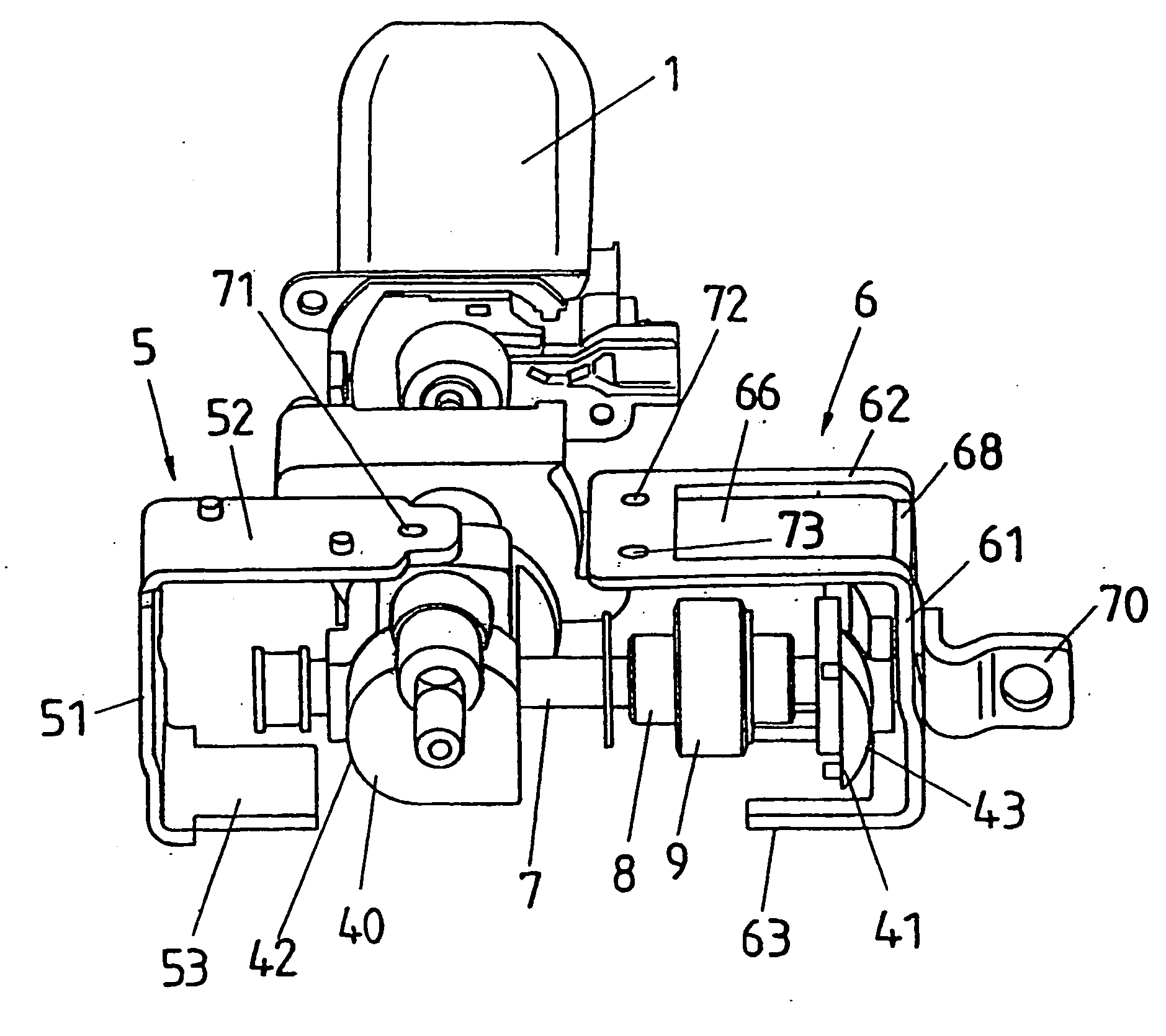
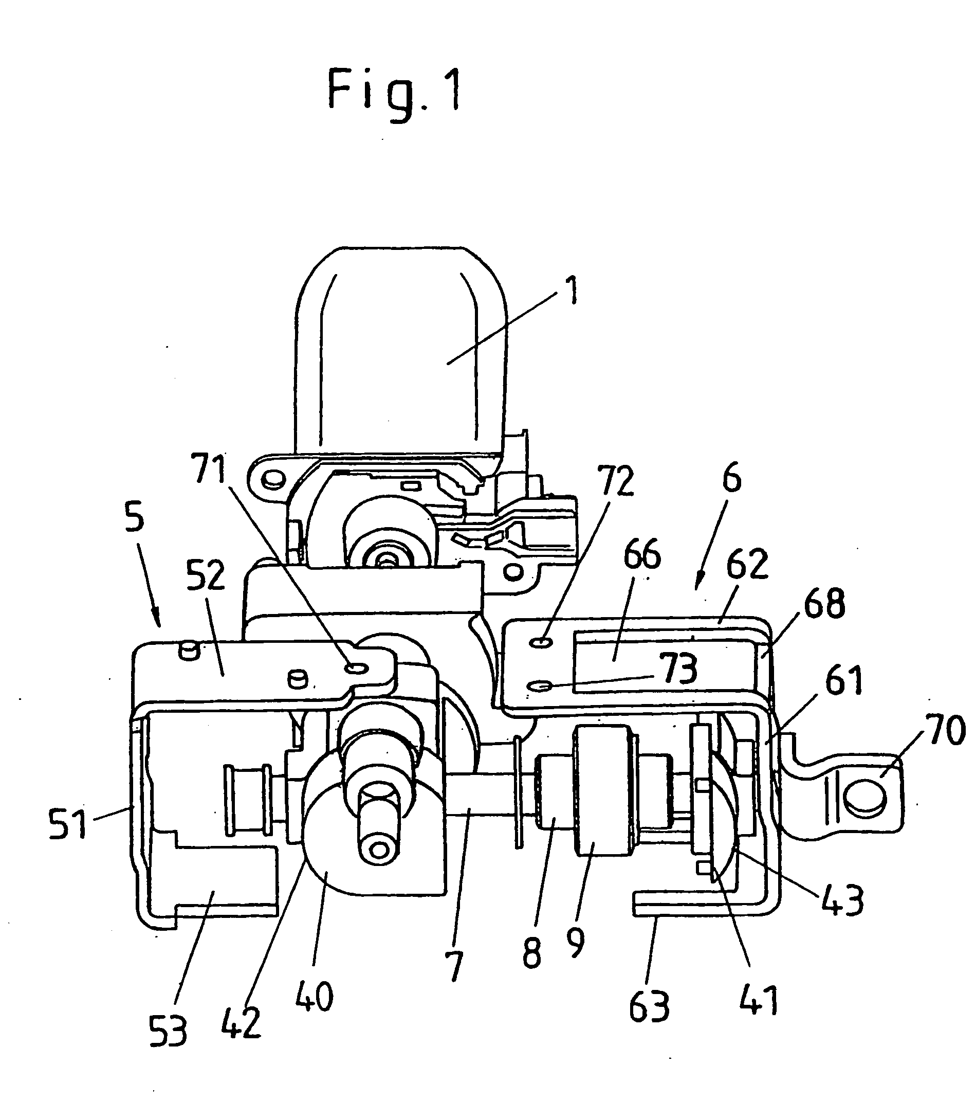
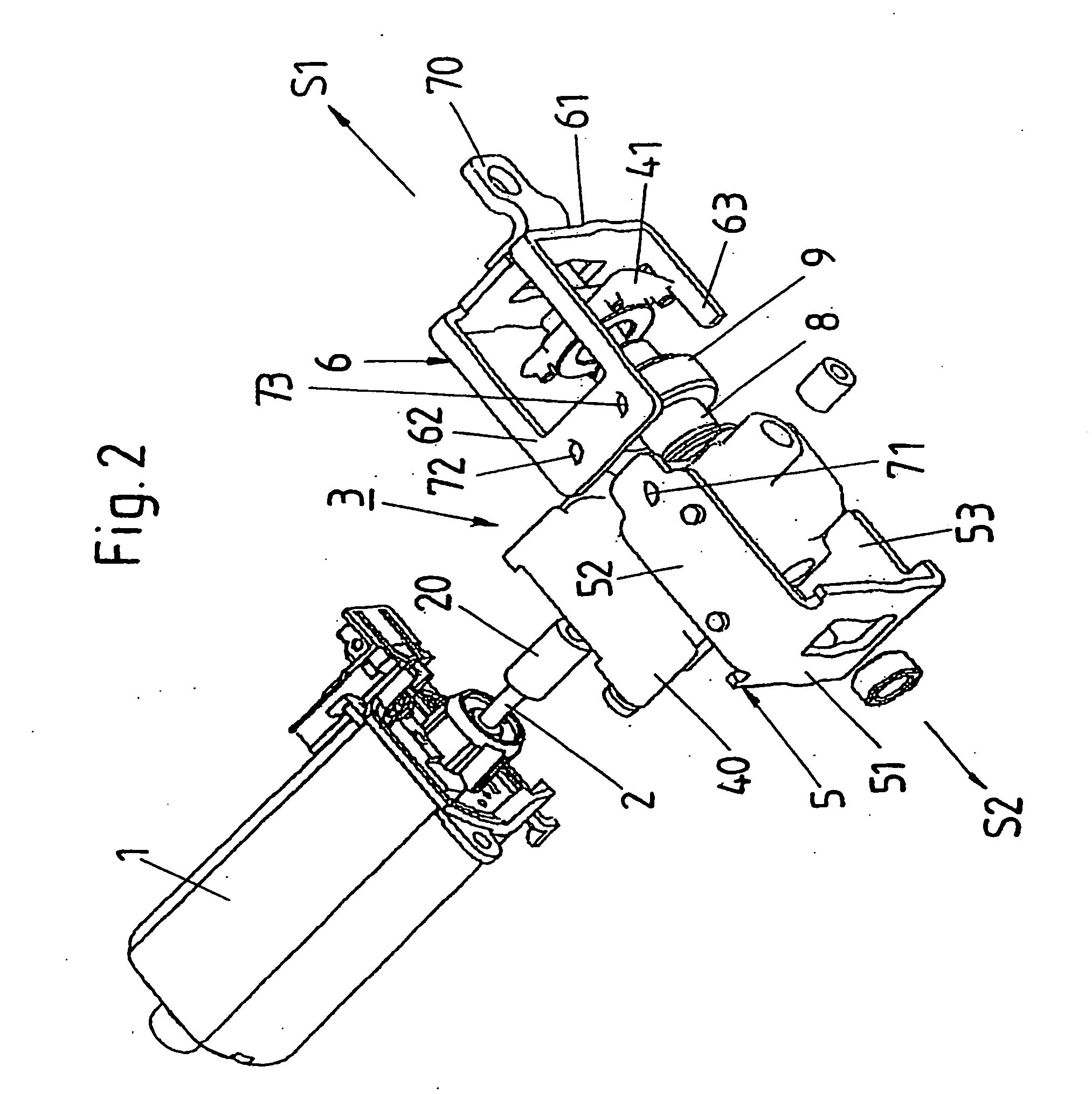
[0046] The spindle drive which is shown in exploded views in FIGS. 1 to 3 has an electric motor 1 whose motor shaft 2 is connected to a drive worm 20 which meshes with a worm wheel 9 of a gear mechanism 3. The worm wheel 9 is connected to a spindle nut 8 whose thread meshes with the thread of a spindle 7. Any rotation of the motor shaft 2 is transferred through the drive worm 20 to the worm wheel 9 and thus to the spindle nut 8 which is connected in one piece to the worm wheel 9 so that when the spindle 7 is mounted rotationally secured it changes its position in relation to the motor shaft 2 through the rotation of the spindle nut 8, i.e. is moved in the direction S1 or S2 in relation to the motor shaft 2 according to FIG. 2 depending on the direction of rotation of the electric motor 1.

[0047] The gear elements, drive worm 20, spindle 8 and worm wheel 9, are combined into the gear mechanism 3 which has a gear housing 4 which consists of a housing shell 40 and a housing cover 41 wh...


PUM


Abstract

A spindle or worm drive for adjustment devices in motor vehicles. The device is secured with a fixed spindle or a fixed toothed rack to the first of two parts which can be adjusted in relation to each other, and is provided with a gear mechanism which is connected to the second of the two parts which can be adjusted in relation to each other. The gear housing is free from backlash and is enclosed by at least one bearing shell such that it is pivotable about at least one axis. The bearing shell consisting of two bearing plates which fit into one another and which can be joined to each other after enclosure of the gear housing. The gear housing is made of plastic and is provided with a concave or convex housing part which is surrounded by a convex or concave bearing shell section made of a material which is suitable for receiving crash forces, especially a metal material.

Description

CROSS-REFERENCE TO RELATED APPLICATION [0001] This application is a National Phase Patent Application of International Application Number PCT / DE2002 / 04282, filed on Nov. 18, 2002, which claims priority of German Patent Application Number 102 06 524.1, filed on Feb. 13, 2002, and German Patent Application Number 102 50 994.8, filed on Oct. 30, 2002.BACKGROUND [0002] The invention relates to a spindle or worm drive for adjustment devices in motor vehicles, more particularly for seat adjustment devices, window lifters and sliding roofs. [0003] From DE 198 61 100 A1 a spindle drive is known for adjustment devices in motor vehicles having a fixed spindle which is fixed on a first of two relatively rotatable parts, a gearing mechanism which is mounted on the second of the relatively rotatable parts, and a gear housing for accommodating the gearing. The gear housing consists of two housing plates which are fixed against each other by means of push-fit connections and which are designed as ...

Claims


Application Information

Patent Timeline
Patent Type & Authority Applications(United States)
IPC IPC(8): B60J7/10B60N2/02B60N2/06B60N2/90E05F15/16F16H1/16F16H57/025H02K7/116
CPCB60J7/10E05F15/697B60N2/0232B60N2/067B60N2/443E05Y2900/542E05Y2900/55F16H1/16F16H57/025H02K7/1166B60N2002/0236Y10T74/18664Y10T74/2186Y10T74/18808E05F15/689B60N2/0224B60N2/1853B60N2/929B60N2/02253B60N2/02246
Inventor DOHLES, DITTMARBREHM, HORSTHOFMANN, JOCHENKRONER, GREGORFISCHER, MARKUS
Owner BROSE FAHRZEUGTEILE GMBH & CO KG
Why Eureka
Try Eureka