Near real time arc welding monitor

a monitor and arc welding technology, applied in welding accessories, welding apparatus, manufacturing tools, etc., can solve the problems of difficulty in maintaining the proper arc length of arc welding, and the instructor cannot monitor the cues

Inactive Publication Date: 2005-06-16
SPENCER MARK SCOTT
View PDF5 Cites 86 Cited by
  • Summary
  • Abstract
  • Description
  • Claims
  • Application Information

AI Technical Summary

Benefits of technology

[0008] A further object of the present invention is to provide the arc welding student with a visual, graphic depiction of the weld arc length, speed, and quality so that the instructor and student can study the student's welding technique and make corrections. A further objective of the present invention is to allow the instructor to analyze the data gathered by the welding monitor using standard statistical analysis tools to statistically grade the weld quality. Keeping a record of these statistical grades in a portfolio of welds accomplished by the arc welding student would allow the instructor to infer performance trends, identify arc welding student performance shortfalls, and develop and provide remedial instruction as necessary. A further object of the present invention is to provide the arc welding student with a portfolio of weld performance that can be used as an archival record of welding skill and ability.
[0009] A still further object of the present invention is to provide a means to unobtrusively inspect the quality of individual welds as the welds are being produced on the job site. The near-real-time inspection capability of the present invention can provide indicators that additional; more intrusive, detailed, and costly inspections of welds are warranted. An archival record of individual welds accumulated by the use of the present invention can serve as forensic evidence in quality assurance investigations.

Problems solved by technology

However, a student learning arc welding frequently finds it difficult to maintain the proper arc length due to the judgment factors associated with interpreting the various sensory indicators (sights and sounds of welding).
These efforts produce feedback that is usable only during the welding process; there is no record of the weld that can be used for further analysis after the welding event.
The visual cues provided in one system add a distraction during the welding process and an instructor cannot monitor the cues.

Method used


Image

  • Near real time arc welding monitor
  • Near real time arc welding monitor
  • Near real time arc welding monitor

Examples


Embodiment Construction

[0021] The following description of the preferred embodiments is presented to illustrate the present invention and is not to be construed to limit the scope of the appended claims in any way.

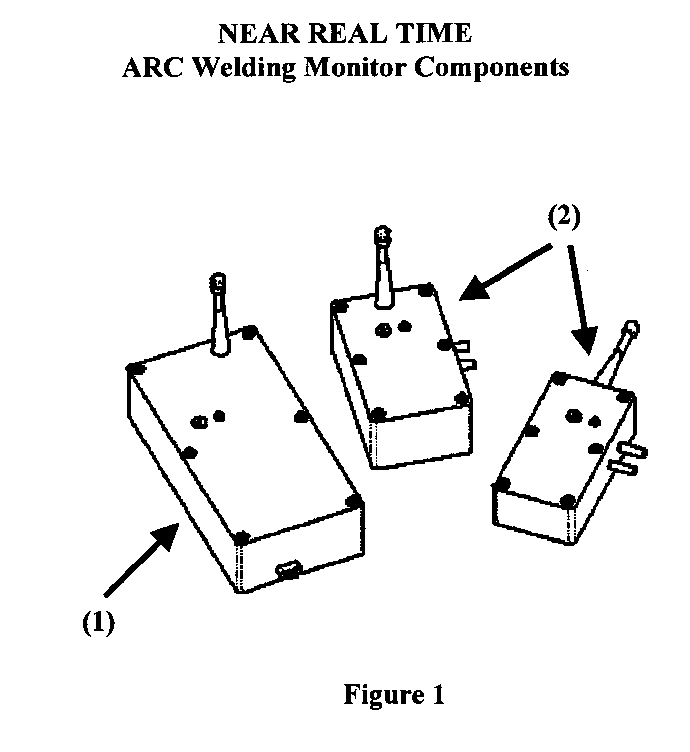
[0022] Typical physical protective enclosures of the present invention receiver and display component (1) and the sensor and transmitter component (2) are represented in FIG. 1.

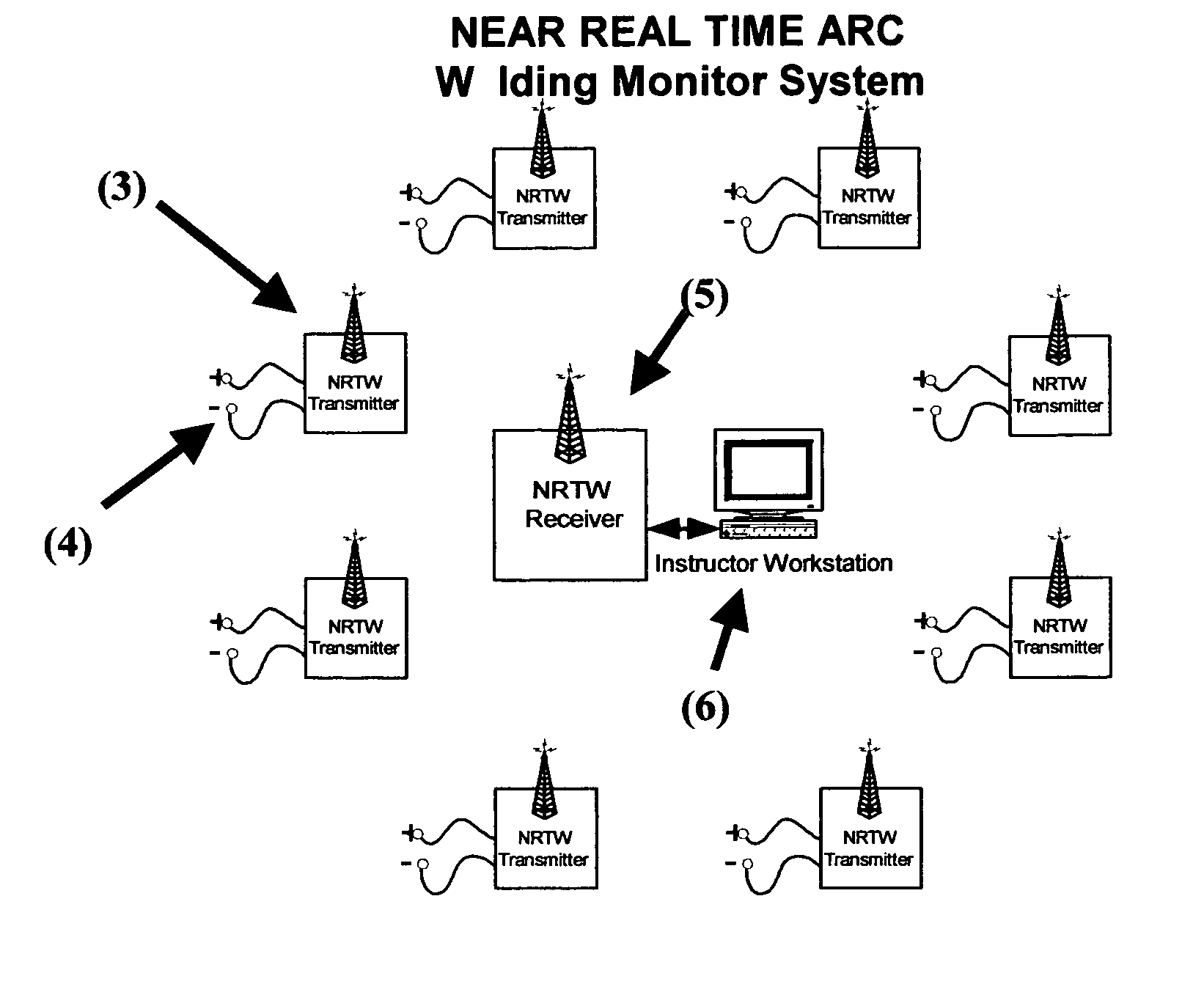
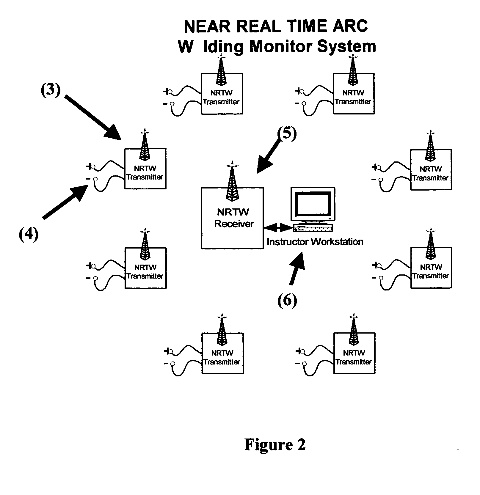
[0023] The overall depiction of the present invention is illustrated in the block diagram of FIG. 2. Individual welding monitor sensor and transmitter components are attached to the arc welding equipment located at arc welding workstation locations (3). The welding monitor is connected to the electrical output leads of the arc welding equipment (4) and the arc welder operator turns on the welding monitor to transmit on a pre-determined radio frequency channel. The arc weld operator then begins to weld.

[0024] The receiving and display component (5) of the present invention is located within reception range of the weldin...


PUM

PropertyMeasurementUnit
voltageaaaaaaaaaa
currentaaaaaaaaaa
transmit voltageaaaaaaaaaa

Abstract

An arc welding monitor designed to aid in the instruction of electric arc welding, provide data that can be used for inspection and quality assurance of individual welds, and provide an archive record of the arc welding process for future reference and analysis. A sensor is used to unobtrusively measure the welding arc parameters. The measurements are transmitted in real-time from the welding station to an instructor/supervisor workstation via a radio frequency data link. The received data is graphically displayed in near-real-time on the instructor/supervisor workstation computer screen. The data can be analyzed by standard statistical analysis tools to qualitatively grade the weld, be stored on computer disk storage media for later retrieval and analysis, or printed in a graphic display. Interpretation of the graphical display and statistical analysis is used to critique and instruct welder operator technique or to indicate process flaws that warrant further inspection of suspected welds.

Description

CROSS REFERENCE TO RELATED APPLICATIONS [0001] Not Applicable FEDERALLY SPONSORED RESEARCH OR DEVELOPMENT [0002] Not Applicable FIELD OF INVENTION [0003] The invention relates generally to a monitor designed to aid in the instruction of electric arc welding and weld qualitative analysis. The invention pertains to arc welding operations manually controlled by a welder using both AC and / or DC welding equipment. The voltage, current, and other parameters of the arc during the welding process are monitored and the data is transmitted from the welding station to a personal computer located at a remote instructor / supervisor workstation via a radio frequency data link system. The data is graphically displayed in near-real-time on the personal computer screen at the instructor / supervisor workstation. Once the data is uploaded into the personal computer, the data is analyzed with standard statistical analysis techniques to provide a qualitative grade of the weld. The analyzed data is used fo...

Claims


Application Information

Patent Timeline
Patent Type & Authority Applications(United States)
IPC IPC(8): B23K9/095B23K9/10B23K9/32
CPCB23K9/095B23K9/0956B23K9/32B23K9/1087B23K9/10
Inventor SPENCER, MARK SCOTT
Owner SPENCER MARK SCOTT
Why Eureka
Try Eureka