Magnetic tape cartridge

a technology of magnetic tape and cartridge, which is applied in the direction of driving by direct/indirect member action, recording information storage, instruments, etc., can solve the problems of reduced operability, inability to easily perform, and complicated assembly operation, so as to prevent the magnetic head from being charged with electricity, reduce the specific surface resistance, and prevent the effect of static electricity damag

Inactive Publication Date: 2005-06-16
FUJIFILM CORP
View PDF13 Cites 9 Cited by
  • Summary
  • Abstract
  • Description
  • Claims
  • Application Information

AI Technical Summary

Benefits of technology

[0036] The first magnetic tape cartridge of the present invention has the following advantages:
[0062] Also, if the thickness of the leader tape joined to the leading end of magnetic tape is less than or equal to five times the thickness of the magnetic tape, a stepped portion in the joint portion between them becomes small. Therefore, the tape transfer onto the stepped portion due to deformation caused by winding of the magnetic tape can be reduced; a tape end region, which has a possibility of dropout and in which no magnetic recording is performed, can be made shorter; reliability of magnetic recording quality can be enhanced; and recording capacity can be increased. In this way, the second object of the present invention mentioned above is achieved.

Problems solved by technology

However, the aforementioned mechanism has the problem that assembly of the releasing member with respect to the reel is troublesome and therefore operability will be reduced.
This structure, however, has the problem that the assembly, which involves inserting the releasing member into the center opening of the reel and then inserting the leg portions into the through holes, cannot be easily performed.
More specifically, in the case where the size of the center opening in the reel is smaller than that of a portion of the cartridge case in which the releasing member is housed, and the releasing member cannot be assembled in a horizontal posture, the assembly operation becomes complicated and troublesome and the operation of forcibly pushing the releasing member is required.
Thus, the aforementioned structure has the problem that it is disadvantageous in durability.
However, the plastic material is easily charged with static electricity by friction, etc., and therefore there is a fear that the magnetic head will be damaged by this static electricity.
Particularly, the newer magnetic heads for magnetic recording and reproduction are likely to be damaged by static electricity, because high-sensitivity magnetic heads such as an MR head, etc., are used to obtain high recording density.
Because of this, tape strength is reduced, the tape edge is likely to be damaged by contact with the flange portions of tape guides during load and unload operations, and there is a fear that tape will be cut by repeated use.
Furthermore, there is a fear that the first part of the magnetic tape to be wound on the machine reel of the magnetic recording-reproducing unit will also be damaged when bent and that the strength of that part will be reduced.
Because of this, the tape surface becomes flat and smooth, the friction coefficient becomes low, and it is difficult to obtain sufficient clamping force between the magnetic tape and the leader member.
This causes a dropout phenomenon in which suitable writing and reading of data cannot be performed, and results in defects in magnetic recording quality.
However, if this region is long, recording capacity will be reduced.

Method used


Image

  • Magnetic tape cartridge
  • Magnetic tape cartridge
  • Magnetic tape cartridge

Examples


first embodiment

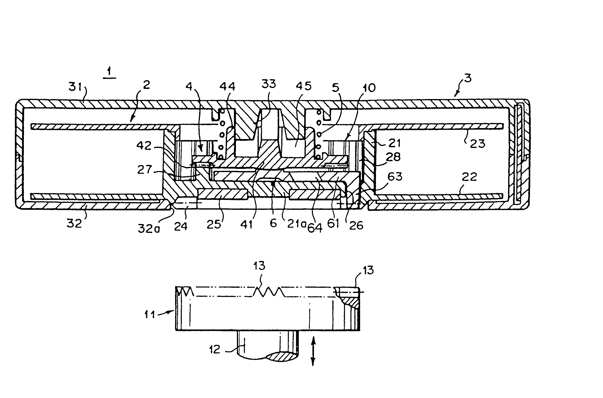
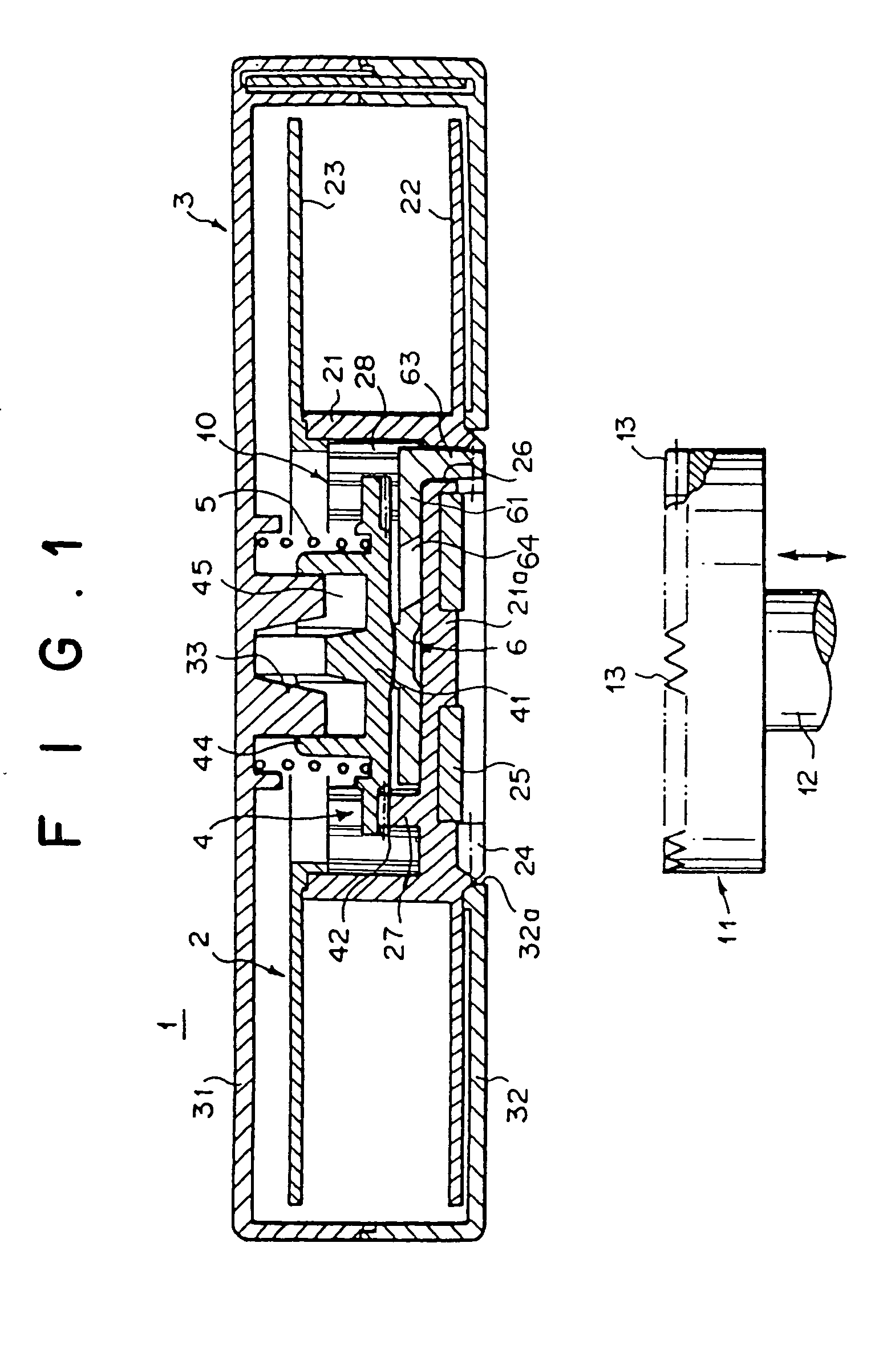
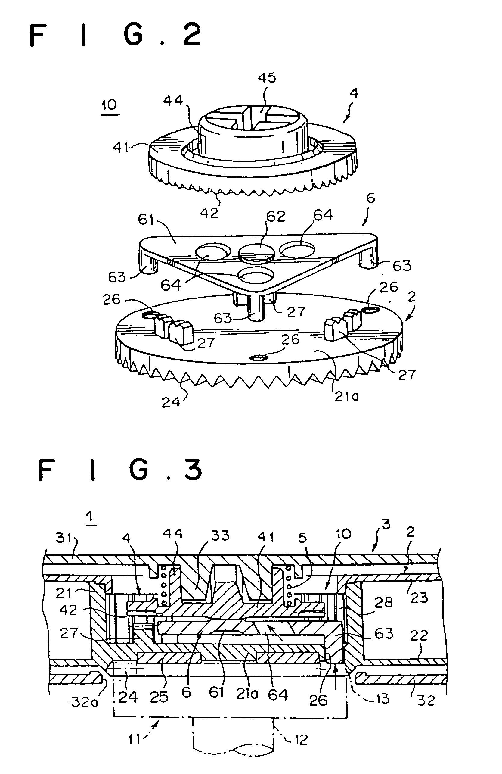
[0078] The present invention will hereinafter be described in detail with reference to embodiments shown in the drawings. FIG. 1 shows a sectional view of a magnetic tape cartridge constructed according to the present invention achieving the aforementioned first object of the invention, the tape cartridge being in an inoperative state. FIG. 2 shows an exploded perspective view of the essential parts of the magnetic tape cartridge of FIG. 1; FIG. 3 shows a sectional view of the essential parts of the magnetic tape cartridge of FIG. 1 being in an operative state; and FIG. 4 shows a plan view of an releasing member being in an assembled state.

[0079] The magnetic tape cartridge 1 is constructed so that a single reel 2 with magnetic tape (not shown) wound thereon is rotatably housed within a cartridge case 3. The cartridge case 3 is formed by fastening an upper case 31 and a lower case 32 which has a center opening 32a, with small screws, etc. The magnetic tape cartridge 1 is equipped wi...

second embodiment

[0100]FIG. 9 shows a perspective view of a magnetic tape cartridge of the present invention achieving the aforementioned second object of the invention, with the magnetic tape pulled out. FIG. 10 shows an exploded perspective view of parts by which the leader pin is firmly attached,

[0101]FIG. 11 shows a plan view of the joint portion between magnetic tape and leader tape, and FIG. 12 shows a schematic diagram of the state in which the magnetic tape cartridge has been loaded into a magnetic recording-reproducing unit. Note that the second embodiment uses a leader pin as a leader member.

[0102] The magnetic tape cartridge 101 has a cartridge case 102, which is formed by fastening an upper case 102a and a lower case 102b together with small screws, etc. Within the cartridge case 102, a single reel 105 with magnetic tape 107 wound thereon is rotatably housed. The leading end of the magnetic tape 104 is joined to leader tape 107 firmly attached to a leader pin (leader member) 103. One si...

third embodiment

[0111] the leader tape 107 is constructed so that the thickness of the leader tape 107 is less than or equal to 5 times that of the magnetic tape 104. That is, as shown in FIG. 11, at the part where the magnetic tape 104 and the leader tape 107 are joined together by the splicing tape 107a, the thickness b of the leader tape 107 is greater than the thickness a of the magnetic tape 104. The dimensions of the magnetic tape 104 and the leader tape 107 are set so that a ratio (b / a) between them is 5 times or less (≦5), preferably 3 times or less, and further preferably 2 times or less.

[0112] If the thickness ratio between the magnetic tape 104 and the leader tape 107 is made relatively small, the stepped portion in the joint portion between them can be made smaller; the tape transfer onto the stepped portion due to deformation caused by winding of the magnetic tape 104 can be reduced; a tape end region, which has a possibility of dropout and in which no magnetic recording is performed, ...


PUM

PropertyMeasurementUnit
Raaaaaaaaaaa
specific surface resistanceaaaaaaaaaa

Abstract

A magnetic tape cartridge with an improved reel-rotation restraining mechanism is disclosed. The reel-rotation restraining mechanism has a reel locking member, which is movable toward and away from the reel, for restricting rotation thereof; an urging member for urging the reel locking member in a restraining direction; and an releasing member, which is rotatable integrally with the reel, for moving the reel locking member in an unlocking direction by moving according to a chucking operation of a rotation drive mechanism of a drive unit. The releasing member has three leg portions on the vertexes of a triangular plate portion insertable into through holes in the reel. The releasing member is sized so that with part of the releasing member inserted into a center opening of the reel, and two of the three leg portions positioned near the through holes, the remaining one leg portion can be dropped and inserted within the center opening.

Description

TECHNICAL FIELD [0001] The present invention relates to a magnetic tape cartridge and more particularly relates to the structure of reel-rotation restraining means which causes the reel to be in a rotation-locked state when not being used, and the leader tape joined to the leading end of the magnetic tape, in a magnetic tape cartridge where a single reel with magnetic tape wound thereon is rotatably housed within a cartridge case. BACKGROUND ART [0002] In magnetic tape cartridges, which are being used as storage media that are employed in external storage units for computers, etc., there is known a type where a single reel with magnetic tape wound thereon is rotatably housed within a cartridge case. This magnetic tape is employed to archive data for computers, etc., and stores important information. For this reason, reel-rotation restraining means for restricting rotation of the reel is installed so that problems, such as tape jamming, etc., do not occur and that the magnetic tape i...

Claims


Application Information

Patent Timeline
Patent Type & Authority Applications(United States)
IPC IPC(8): G11B23/04G11B23/107G11B23/26
CPCG11B23/043G11B23/26G11B23/107G11B23/044G11B23/047G11B23/048G11B2220/90
Inventor ISHIKAWA, KENJIYAMAMOTO, HIDETOSHIMORITA, KIYOOHASHIMOTO, AKIHIROTAKAHASHI, DAISUKESHIGA, HIDEAKI
Owner FUJIFILM CORP
Why Eureka
Try Eureka