
System and method for filtering reflected infrared signals

a technology of infrared signal and filtering system, which is applied in the field of accurate sensing of infrared signals, can solve the problems of inaccurate fluid dispensing device, particular problems with the use of ir activated devices that control water flow on faucets, and inability to accurately detect the reflected infrared signal

Inactive Publication Date: 2005-06-16
IBM CORP +1
View PDF4 Cites 40 Cited by
  • Summary
  • Abstract
  • Description
  • Claims
  • Application Information

AI Technical Summary

Benefits of technology

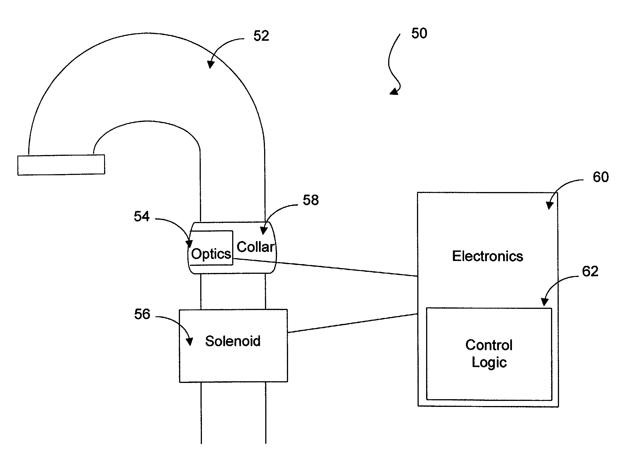
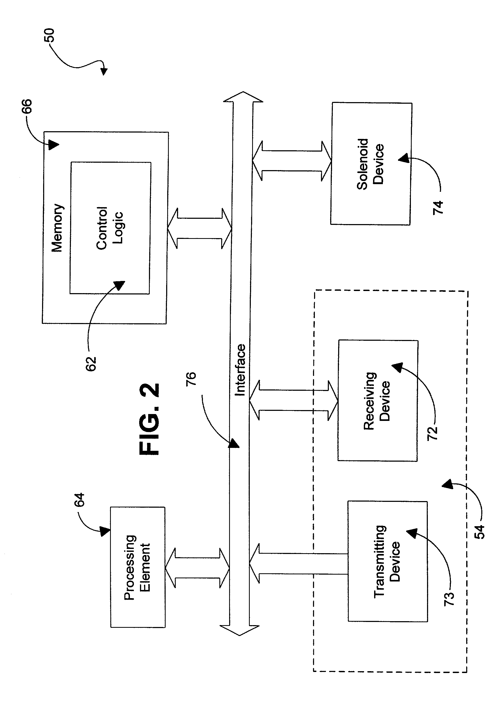
The present invention provides a system and method for controlling a fluid-dispensing device using infrared technology. The system filters out environmental factors that may affect the device's input, allowing it to continue operating even when its input is affected. The control logic activates the solenoid when an IR detection value is received per range setting, and also detects movement within the detection range to control the device. The technical effect of the invention is to provide a reliable and efficient system for controlling fluid dispensing using infrared technology.

Problems solved by technology

IR activated devices that control water flow exhibit particular problems with respect to their use on faucets.
For example, a fluid dispensing device may be inaccurate in that it does not detect an object at different ranges.
For example, if the detection range is set at an unvarying value, then a fluid-dispensing device having a deeper sink may be less accurate in that a user would be required to place his / her hands inconveniently close to the transmitter / receiver pair.
Frequently, water droplets inadvertently splash onto the optics (i.e., the transmitter / receiver pair).
In addition, the fluid-dispensing device may erroneously detect an object outside of the desired detection range if the object is constructed of a thermosteel or other highly reflective material.
Such erroneous detection may cause the inadvertent activation of the solenoid.
Moreover, the proximity of such an object and the material from which such objects are made can contribute to inaccurate behaviors of the automated fluid-dispensing device, particularly when the fluid-dispensing device is configured to vary its detection ranges.
Augmentation of the reflected pulse causes hardware and control logic malfunction.

Method used


Image

  • System and method for filtering reflected infrared signals
  • System and method for filtering reflected infrared signals
  • System and method for filtering reflected infrared signals

Examples


Embodiment Construction

[0018] In general, the present invention provides an IR apparatus and method for filtering an IR reflection signal that may render the optics of an automatically activated fluid dispensing device inoperable. More specifically, an IR apparatus and method, in accordance with the present invention, determines that water accumulation on the sink basin or on the optics is affecting the automatic water activation function of the fluid dispensing device. During a normal operation cycle, an IR pulse is periodically emitted (e.g., every 250 milliseconds). If hands are not within the detection range, then the IR radiation received by the IR apparatus is preferably below an activation threshold. The pulse has a maximum range that includes the sink basin. However, if hands are within the detection range, the reflection of the pulse from the user's hands increases the energy in the pulse reflection that is detected by the IR apparatus. When the IR radiation detected by the IR apparatus exceeds t...


PUM


Abstract

A system for preventing IR reflection ghosting in a fluid-dispensing device having a transmitter / receiver pair and control logic. The control logic interfaces with the transmitter and the receiver, activating the fluid-dispensing device when an object is present within the transmitter detection range by comparing a set predefined value with the IR value obtained. When the reflection is above the detection level, the control logic further evaluates two consecutive pulses to detect movement between said two consecutive pulses. An increase in IR value indicates movement, thereby causing the fluid-dispensing device to be activated.

Description

CROSS-REFERENCE TO RELATED APPLICATIONS [0001] This application claims the benefit of U.S. Provisional Patent Application Ser. No. 60 / 267,441 entitled, “Remotely Managed Automatic Dispensing Apparatus and Method”, filed on Feb. 8, 2001, and U.S. Provisional Patent Application Ser. No. 60 / 240,898 entitled, “Remotely Managed Automatic Dispensing Apparatus and Method”, filed on Oct. 24, 2000, both of which are hereby incorporated by reference herein.BACKGROUND OF INVENTION [0002] 1. Field of the Invention [0003] The present invention relates generally to the field of infrared (IR) reflection sensing, and more particularly to the accurate sensing of a reflected infrared signal that may be effected artificially due to a change in the environment of the reflection field of an infrared transmitter. [0004] 2. Technical Background [0005] Infrared transmitter / receiver pairs are typically employed to electronically control water flow through a fluid-dispensing device such as a faucet or spicke...

Claims


Application Information

Patent Timeline
Patent Type & Authority Applications(United States)
IPC IPC(8): F16K31/02H04B13/00
CPCH04B13/00
Inventor WATSON, THOMAS J.
Owner IBM CORP
Learn More