Semiconductor device and method of fabricating the same

a semiconductor memory device and semiconductor technology, applied in the direction of semiconductor memory devices, electrical devices, transistors, etc., can solve the problems of reducing the size of the semiconductor memory device, affecting the operation of the device, so as to prevent the occurrence of dishing or the like, increase the chip area, and the effect of increasing the chip area

Inactive Publication Date: 2005-06-16
KK TOSHIBA
View PDF10 Cites 69 Cited by
  • Summary
  • Abstract
  • Description
  • Claims
  • Application Information

AI Technical Summary

Benefits of technology

[0020] Therefore, an object of the present invention is to provide a semiconductor device in which an increase in the chip area and occurrence of dishing or the like can be prevented although trench isolating regions with different depths are formed and a method of fabricating such a semiconductor device.

Problems solved by technology

However, either method requires a large width of trench isolating region in order that a large element isolation width may be ensured or a stopper region may be formed, resulting in a problem that an area for the element isolation is increased.
However, the STI technique forming a trench isolating region with a depth in accordance with the withstand pressure results in the following new problem: a non-volatile memory generally comprises a memory cell and a peripheral circuit.
Consequently, there is a definite limit in the reduction in the size of the semiconductor memory device.
In such a case as described above, there is a possibility that the CMP process, when carried out, may cause dishing in the trench isolating region 12 formed in the boundary region 4 between the high withstand pressure circuit region 3 and the memory cell region 2, resulting in a problem of abnormal shape.
However, the number of dummy patterns needs to be increased with increase in the degree of dishing, whereupon a new problem arises that an area of the cell (or chip size) should be increased.

Method used


Image

  • Semiconductor device and method of fabricating the same
  • Semiconductor device and method of fabricating the same
  • Semiconductor device and method of fabricating the same

Examples


Embodiment Construction

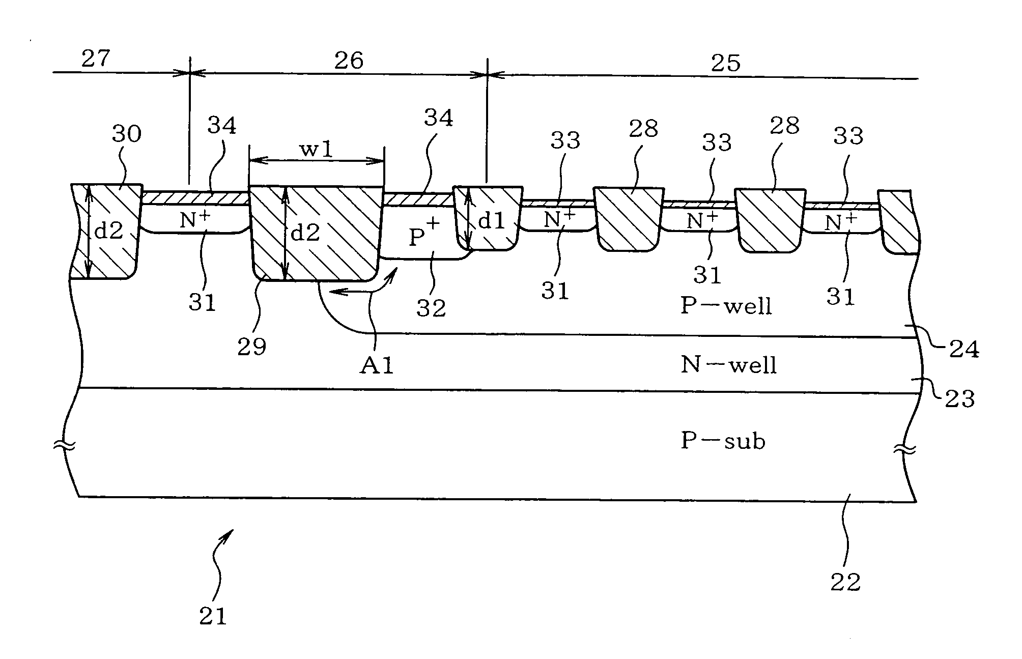
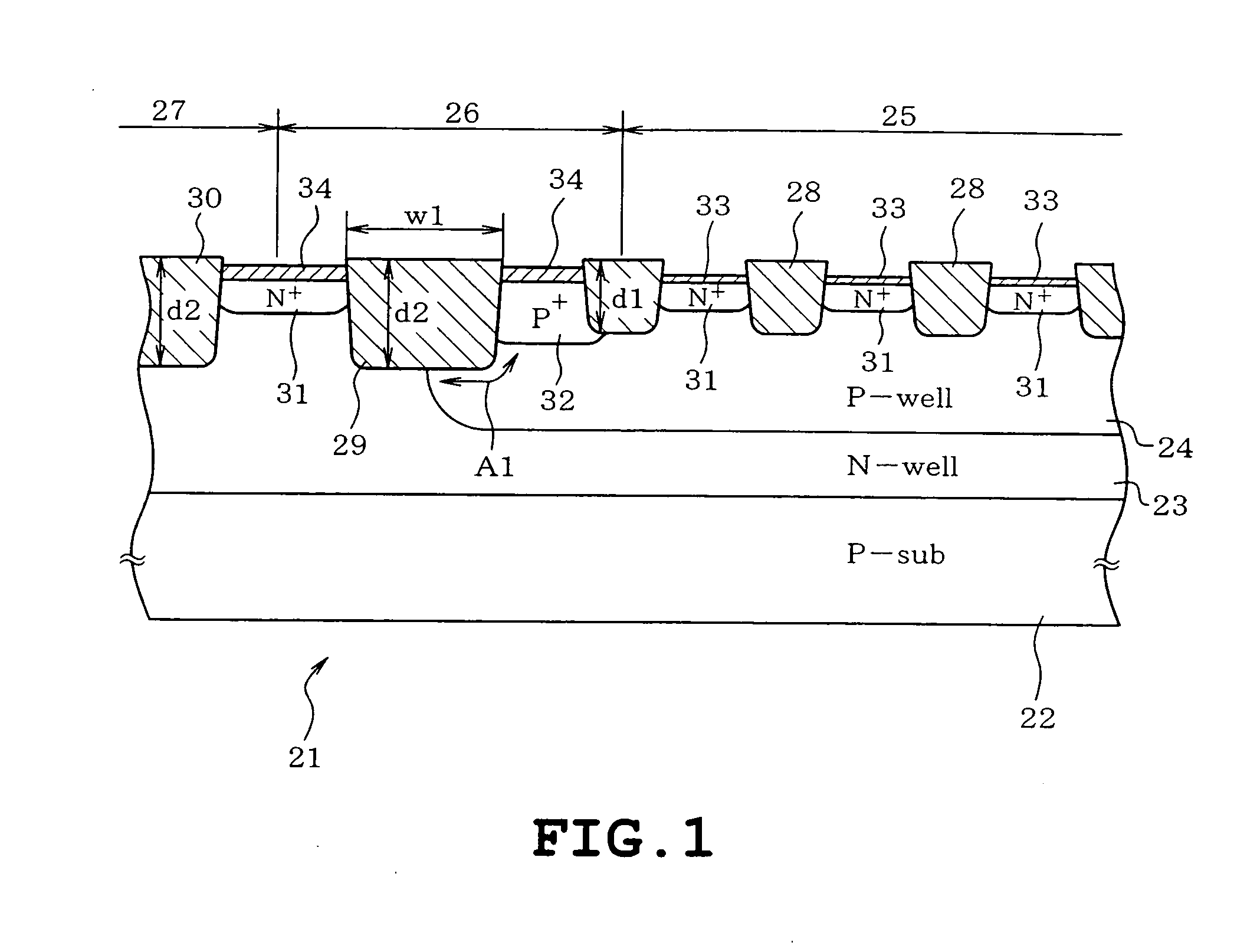
[0034] One embodiment of the present invention will be described with reference to the accompanying drawings. In the following embodiment, the invention is applied to a semiconductor device represented by a flash memory (non-volatile memory) in which elements are isolated by a self-aligned STI method in which an STI doping process is carried out after formation of gate dielectric films.

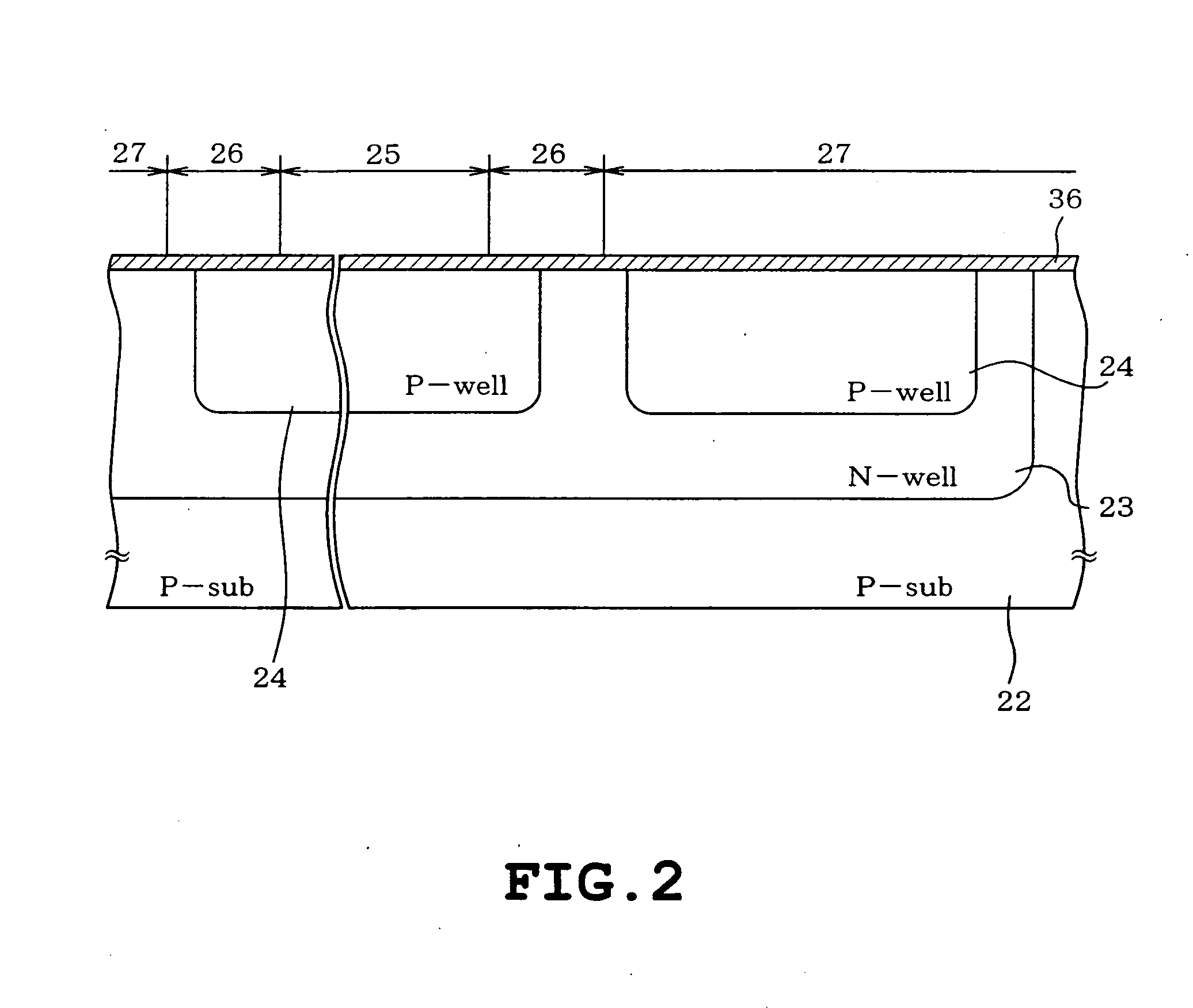
[0035] Referring to FIG. 1, the structure of a non-volatile memory 21 is shown as a semiconductor device fabricated by the fabricating method as will be described later. A p-type (a first conduction type) silicon substrate (P-sub) 22 serving as a semiconductor substrate is formed with an N-well 23 serving as a first well. A P-well 24 serving as a second well is formed in the N-well 23. A memory-cell forming region 25 is formed in the P-well 24. A boundary region 26 is formed in a peripheral portion of the P-well 24. A peripheral circuit 27 is formed outside the P-well 24. The peripheral circuit regio...


PUM


Abstract

A semiconductor device includes a semiconductor substrate of a first conduction type, a first well of a second conduction type formed on the semiconductor substrate, a plurality of second wells of the first conduction type provided in the first well for forming memory cells and a peripheral circuit respectively, each second well having a first depth, a first trench isolating region formed so as to isolate an element within the second well for the memory cells and having a first depth, a guard-ring diffusion region of the first conduction type provided in the vicinity of a peripheral edge of each second well for the memory cells and doped with a high density impurity so as to encompass a forming region of the memory cells, a second trench isolating region formed so that a p-n junction of each second well terminates on a bottom thereof in the vicinity of an outside of the guard-ring diffusion region, the second trench isolating region having a second depth larger than the first depth of each second well, and a third trench isolating region isolating an element formed in each second well for the peripheral circuit, the third trench isolating region having the second depth.

Description

CROSS-REFERENCE TO RELATED APPLICATIONS [0001] This application claims priority to Japanese patent application No. 2003-376816, the content of which is incorporated hereinto by reference.BACKGROUND OF THE INVENTION [0002] 1. Field of the Invention [0003] The present invention relates to a semiconductor device employing a shallow trench isolation structure (STI) as an element isolating structure and a method of fabricating the semiconductor device. [0004] 2. Description of the Related Art [0005] A technique of isolating elements has recently been changing from local oxidation of silicon (LOCOS) to shallow trench isolation (STI) for the purposes of high integration and miniaturization in the fabrication process of semiconductor memory devices. In the element isolation technique employing STI, shallow trenches are formed and filled with an isolator so as to be flattened, whereupon a trench isolating region is provided. [0006] Furthermore, in the element isolating technique employing ST...

Claims


Application Information

Patent Timeline
Patent Type & Authority Applications(United States)
IPC IPC(8): H01L21/762H01L21/76H01L21/8234H01L21/8247H01L27/10H01L27/105H01L27/115H01L29/06H01L29/788H01L29/792
CPCH01L21/76229H01L21/823462H01L21/823481H01L29/0619H01L27/11526H01L27/11546H01L27/105H10B41/49H10B41/40
Inventor SAKAGAMI, EIJI
Owner KK TOSHIBA
Why Eureka
Try Eureka