Fail-safe concept for an electromechanical brake

a technology of electromechanical brakes and failure safety, which is applied in the direction of brake control systems, axially engaging brakes, brake systems, etc., to achieve the effect of reducing the failure safety of such brakes and avoiding fatal consequences for the device to be braked

Inactive Publication Date: 2005-06-16
STOP
View PDF9 Cites 49 Cited by
  • Summary
  • Abstract
  • Description
  • Claims
  • Application Information

AI Technical Summary

Benefits of technology

[0006] An object of the present invention therefore is to make available a fail-safe concept for electromechanical brakes with self-reinforcement in order to increase the failure safety of such a brake. In particular, in the event of occurrence of a failure, surely fatal consequences for the device to be braked should be avoided.

Problems solved by technology

In particular, in the event of occurrence of a failure, surely fatal consequences for the device to be braked should be avoided.

Method used


Image

  • Fail-safe concept for an electromechanical brake
  • Fail-safe concept for an electromechanical brake
  • Fail-safe concept for an electromechanical brake

Examples


Embodiment Construction

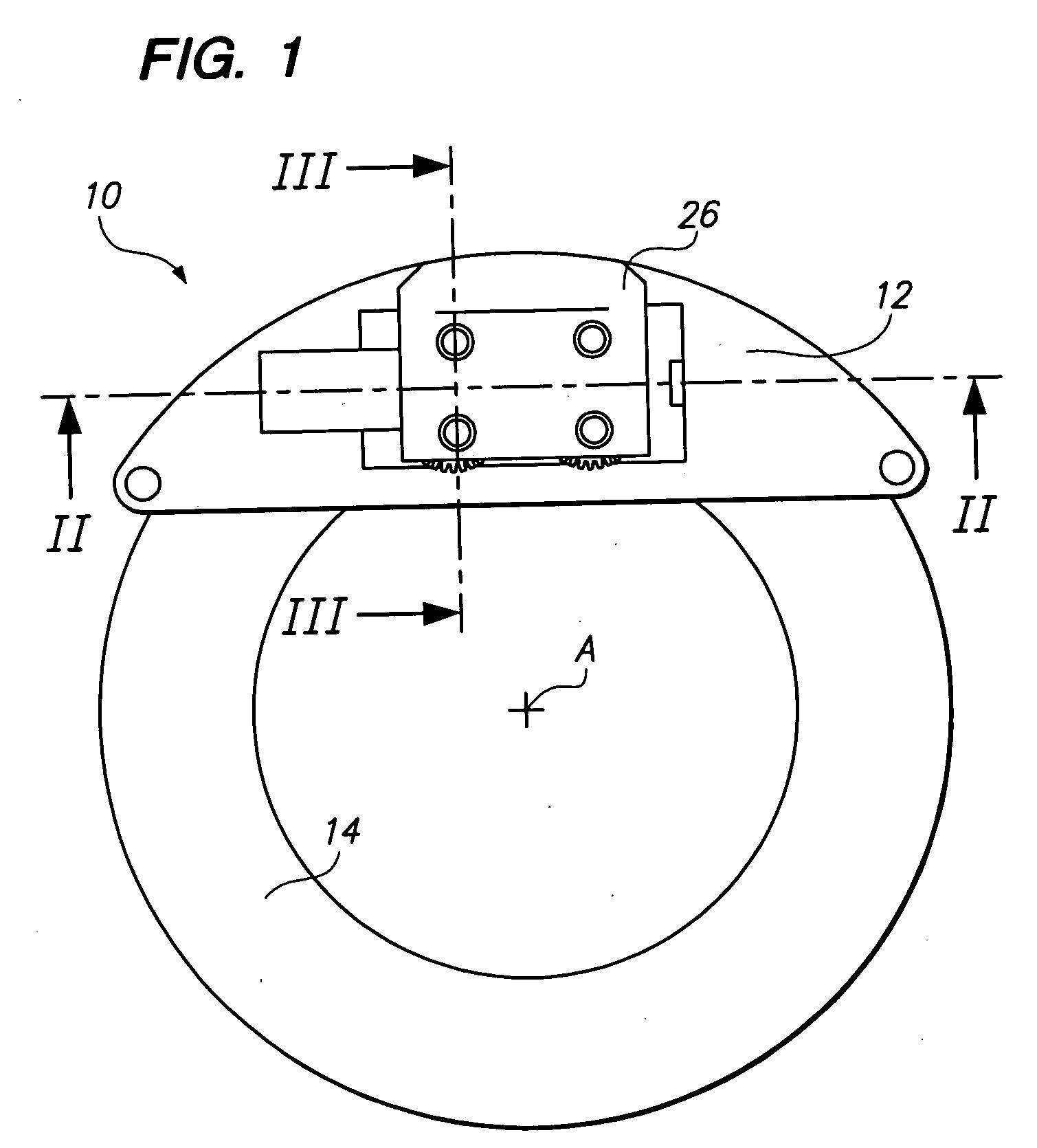
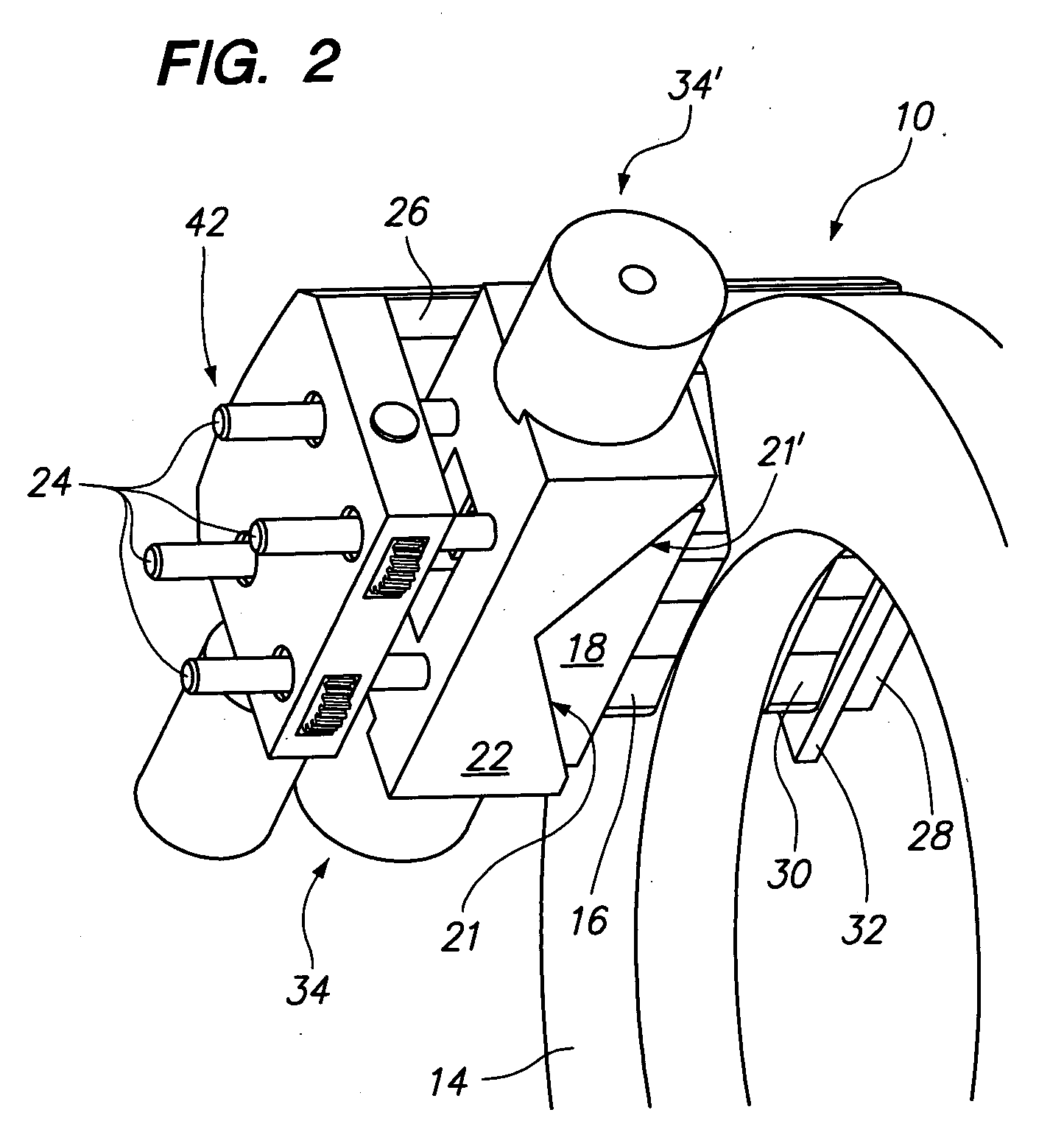
[0020]FIGS. 1 and 2 show an electromechanical brake 10, designed as a disk brake, with a housing 12 and a brake disk 14 rotating about an axis A.

[0021] As can be seen better in FIGS. 3, 4 and 5, the brake 10 has a first friction lining 16, which is firmly joined by for example bonding to the front side of a wedge 18 serving as lining support. On its back side the wedge 18 has, for each direction of rotation of the brake disk 14, a wedge surface 20 and 20′, both of which are assigned to the brake disk 15 at an angle of inclination α and are supported on complementary wedge surfaces 21, 21′ of a block-like support 22.

[0022] The support 22 is held by four threaded bolts 24 on a brake saddle 26 (see FIGS. 2 and 5), which bridges over the brake disk 14 and has an arm 28 pointing toward the axis of rotation. The arm 28 serves to support a second friction lining 30, which is fastened in conventional fashion onto a lining support plate 32, which rests on the inner side of the arm 28 turne...


PUM


Abstract

A control system for an electromechanical brake with self-reinforcement has: means for recognizing a brake failure means for detecting the actual state of motion of the device to be braked and means for opening and closing the brake upon recognition of a failure dependent upon the detected state of motion of the device to be braked. The means for recognizing the state of motion detection in particular the rotational velocity of a brake disk assigned to the brake.

Description

CROSS REFERENCE TO RELATED APPLICATIONS [0001] This is a Continuation of International Application No. PCT / EP03 / 05645 filed May 28, 2003, and published in German but not English as WO 03 / 100282 A1 on Dec. 4, 2003, the priority of which is claimed herein (35 U.S.C. §120) and which claims priority of German Application No. 102 23 768.9 filed on May 28, 2002, the priority of which is also claimed herein. (35 U.S.C. § 119).BACKGROUND OF THE INVENTION [0002] 1. Field of the Invention [0003] The present invention relates to a fail-safe concept for an electromechanical brake with self-reinforcement, in particular a control system for the implementation of a fail-safe concept of this kind. [0004] 2. Description of the Related Art [0005] Electromechanical brakes are known per se, being disclosed for example in DE 198 19 564 C2. Electromechanical brakes of this kind with self-reinforcement have the advantage that an actuating force produced by an electrical actuator is reinforced in a purely ...

Claims


Application Information

Patent Timeline
Patent Type & Authority Applications(United States)
IPC IPC(8): B60T13/74B60T17/22F16D65/14F16D66/00
CPCB60T13/741B60T17/22B60T2270/404B60T2270/413B60T2270/414B60T2270/82F16D2127/10F16D65/568F16D65/72F16D2065/386F16D2121/24F16D2123/00F16D2125/40B60T2270/83
Inventor HARTMANN, HENRYSCHAUTT, MARTIN
Owner STOP
Why Eureka
Try Eureka