
Apparatus for use in measuring fluid levels

a technology for measuring apparatus and fluid level, which is applied in the direction of manufacturing tools, machines/engines, instruments, etc., can solve the problems of affecting the accuracy of measurements, difficult to utilize a traditional straight waveguide rod, and affecting the installation of a measuring device in the fuel tank of a ship

Active Publication Date: 2005-06-16
OHMARTVEGA
View PDF53 Cites 11 Cited by
  • Summary
  • Abstract
  • Description
  • Claims
  • Application Information

AI Technical Summary

Benefits of technology

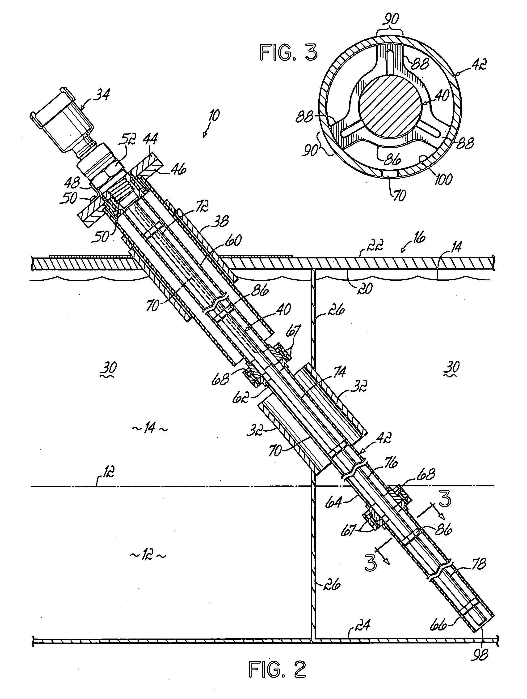
[0005] The present invention provides for a microwave transceiver sensor head that is attached to a waveguide sensor rod which extends longitudinally through a gauge tube. The tube and the rod both extend from the top to the bottom of the fluid tank. They are also comprised of sections, which allows them to be assembled or disassembled in a close quarters environment, such as a lower deck of a ship with minimal headroom. Additionally, the tube has a plurality of circumferentially and longitudinally spaced slots allowing for the equalization of multiple fluids within the tube. The rod is generally radially centered inside and outside the tube by the use of a plurality of spacers, which are attached to notches in the rod. Sections of the tube and the rod can also be curved, facilitating the placement of the measuring device in a tank with a curved bottom, such as a fuel tank defined by a slanted or curved hull of a ship. Finally, since the rod is installed in sections, it can be removed in sections and cleaned, without draining the tank.

Problems solved by technology

However, the installation of a measuring device in a fuel tank of a ship can be problematic.
First, the location of a fuel tank aboard a ship may make it difficult to utilize a traditional straight waveguide rod due to the shape of the hull or other structural considerations such as bulkheads, etc.
In addition, in a salt water environment, problems can develop with regards to keeping a measuring device free from the accumulation of seaborne items that can negatively affect the accuracy of the measurements.

Method used


Image

  • Apparatus for use in measuring fluid levels
  • Apparatus for use in measuring fluid levels
  • Apparatus for use in measuring fluid levels

Examples


Embodiment Construction

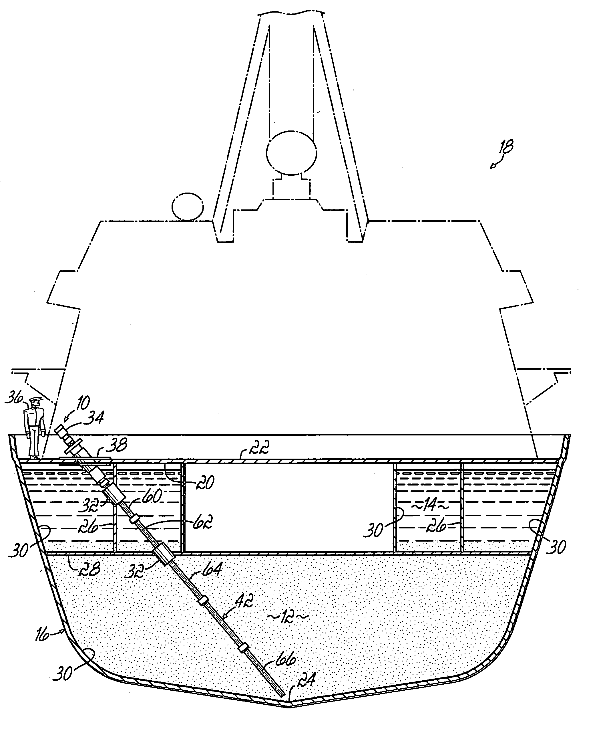
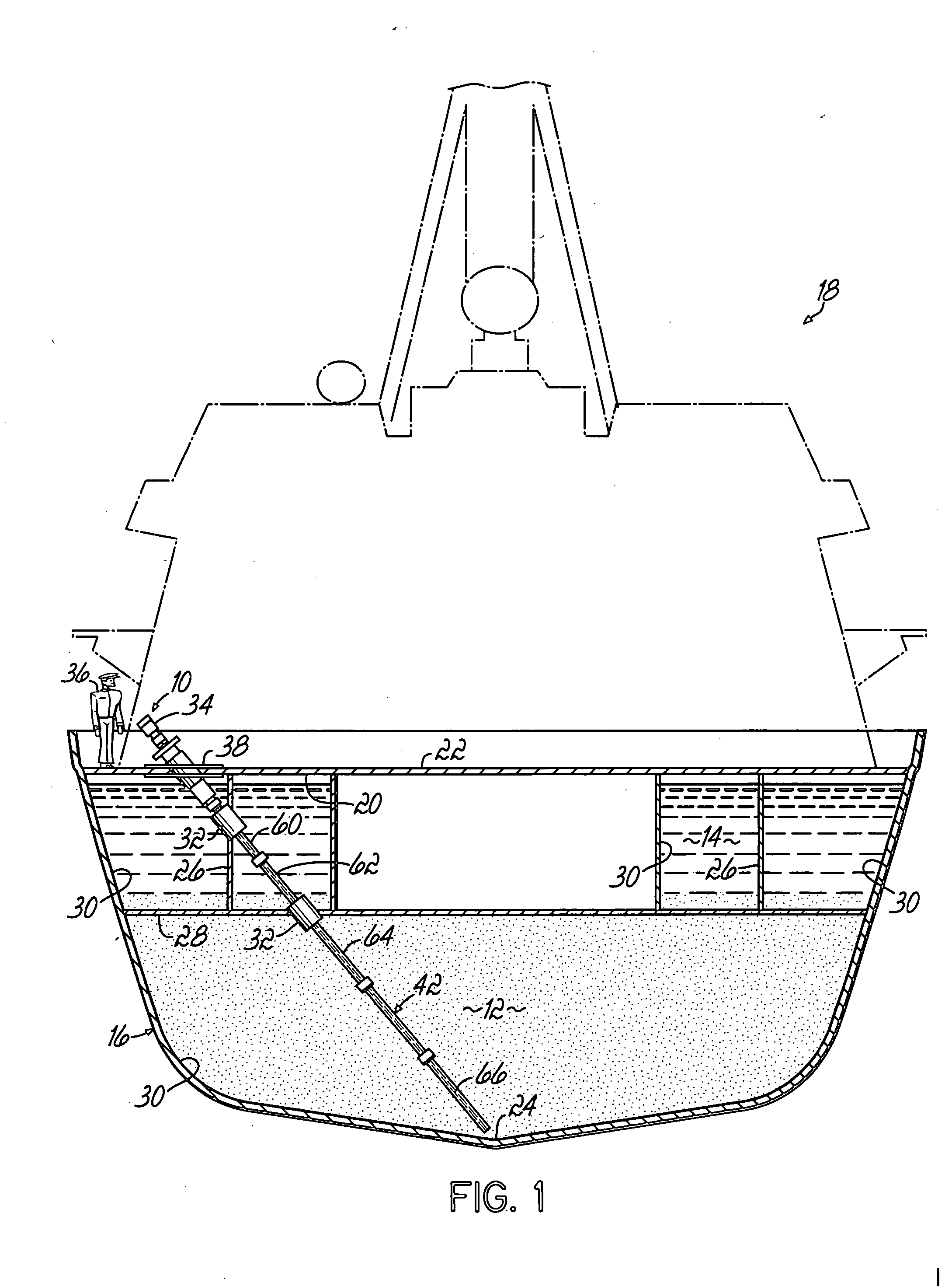
[0015] Referring to the figures and to FIG. 1 in particular, an apparatus 10 for measuring the level of one or more fluids 12, 14 located in a container or tank 16 is shown. Here, the tank 16 is located in a ship 18 but the apparatus 10 could equally be used to measure fluids in other tanks, i.e., tanks used with off-shore oil drilling operations, refinery stacks (also commonly referred to as displacer columns), or airplane fuel tanks.

[0016] The measuring device 10 is configured to measure fluid levels from the top of the fuel tank 20 which as shown, is located below the deck 22 of the ship 18 and also to the very bottom 24 of the fuel tank 16. In a ship 18, this may necessitate passing the measuring device 10 through various bulkheads 26 or other decks 28 which form compartments 30 in the bottom of the ship 18. Accordingly, various sleeves 32 are used to assure that the aperture created in the bulkhead 26 or deck 28 does not adversely affect the structural integrity of the vessel ...


PUM

PropertyMeasurementUnit
widthaaaaaaaaaa
lengthaaaaaaaaaa
widthaaaaaaaaaa

Abstract

A device for use in measuring stratified fluid levels in a container is disclosed. The device has a microwave transceiver sensor head attached to a waveguide sensor rod which is enclosed by a gauge tube. The rod end tubes are comprised of sections which allow them to be assembled or disassembled in a close quarters environment. The tube has a plurality of circumferentially and longitudinally spaced slots providing for the equalization of stratified fluids within the tube. The rod is generally radially centered in the tube by the use of a plurality of spacers which reside in notches in the rod. The spacers are adapted to not penetrate the slots in the tube. The rod can be removed from the tube for cleaning without draining the tank. Additionally, once the rod is removed from the tube, a cleaner brush or scraper can be used to remove any barnacles or other debris from within the tube and the longitudinal slots in the tube.

Description

FIELD OF THE INVENTION [0001] The present invention relates to devices for use in measuring the level of one or more liquids in a container in general, and more particularly, to the measurement of fluid levels in a tank such as a fuel tank of a ship. BACKGROUND OF THE INVENTION [0002] The measuring of the level of a fluid in a tank is important for many reasons. For example, it is important for an operator of a ship or other machine to know the amount of fuel that remains in a fuel tank. Traditionally, mechanical measuring systems and methods such as the use of floats have been used to ascertain the level of a particular liquid in a tank. More recently, a microwave wave guide has been utilized to determine the level of a fluid in a tank. It is also desirable to measure the levels of stratified liquid in a tank. For example, a ship may, for ballast purposes, keep its fuel tanks nearly full at all times by replacing diesel fuel that is burned with seawater. [0003] However, the install...

Claims


Application Information

Patent Timeline
Patent Type & Authority Applications(United States)
IPC IPC(8): G01F23/284
CPCB08B1/008B08B9/00Y10T29/49963G01F23/284Y10T29/49947B08B9/0436B08B1/30
Inventor MOTZER, JUERGENDIETMEIER, JUERGENWILKIE, NEIL T.TOPPUTO, MICHAEL L.
Owner OHMARTVEGA
Learn More