Durable radio frequency indentification label and methods of manufacturing the same

a radio frequency identification and label technology, applied in the field of durable radio frequency identification labels, can solve problems such as cracking or breaking

Inactive Publication Date: 2005-06-16
3M INNOVATIVE PROPERTIES CO
View PDF16 Cites 125 Cited by
  • Summary
  • Abstract
  • Description
  • Claims
  • Application Information

AI Technical Summary

Benefits of technology

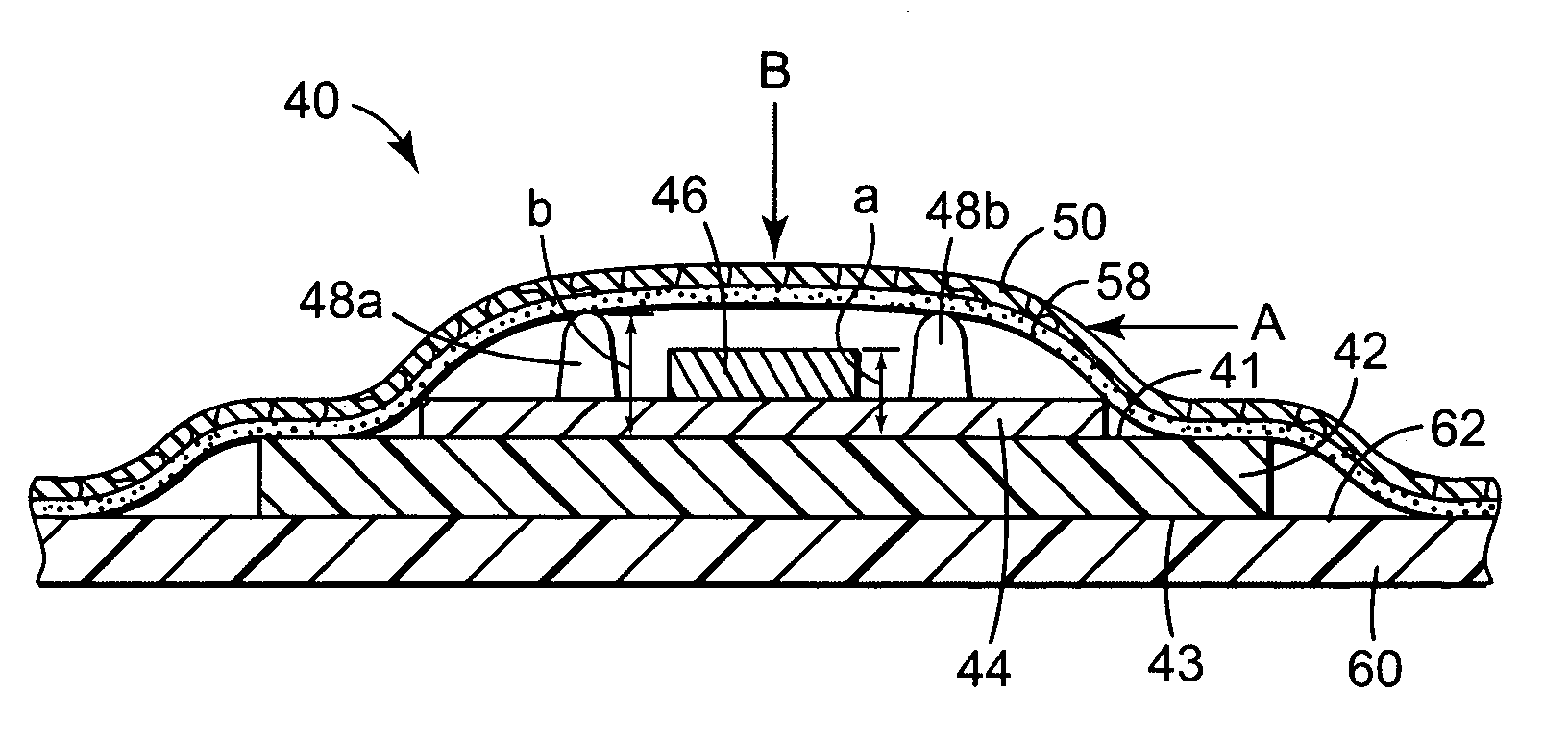
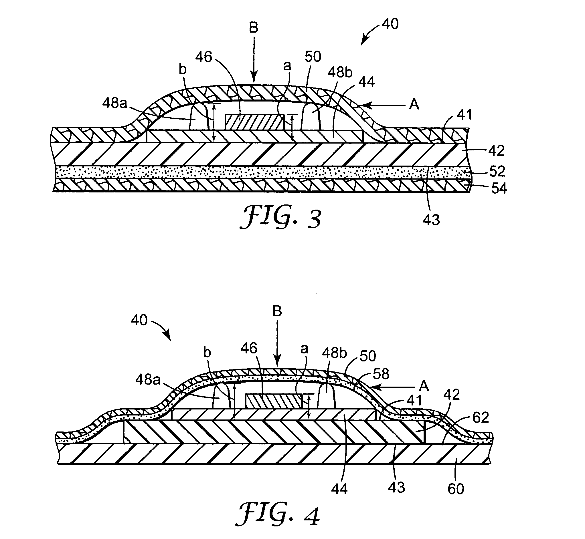
[0008] In another preferred embodiment of the above durable radio frequency identification tag, the flexible substrate has an overall thickness of between 25 microns and 100 microns. In another preferred embodiment of the above durable radio frequency identification tag, the tag further comprises a flexible cover layer attached to the thermoplastic guard and to the substrate. In one aspect of this embodiment, the tag further comprises a second layer of adhesive between the flexible cover layer and the flexible substrate. In another aspect of this embodiment, a pressure of at least at about 1 MPa is applied to the durable radio frequency identification tag adjacent the thermoplastic guard, and the integrated circuit is not damaged. In another preferred embodiment of the above durable radio frequency identification tag, the tag further comprises a liner attached to the first layer of adhesive opposite the substrate.

Problems solved by technology

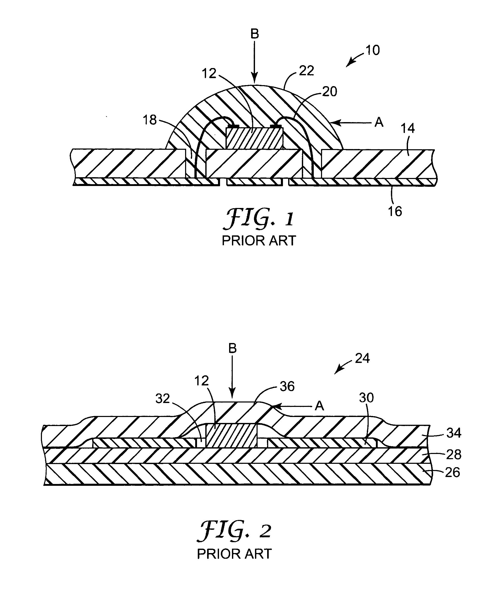
The integrated circuit embedded in the smart card is typically made from brittle silicon, which may crack or break when subjected to certain mechanical forces.

Method used


Image

  • Durable radio frequency indentification label and methods of manufacturing the same
  • Durable radio frequency indentification label and methods of manufacturing the same
  • Durable radio frequency indentification label and methods of manufacturing the same

Examples


example 1

[0076] Commercially available RFID tags from Texas Instruments of Dallas, Tex., under the trade names TAG-IT ISO and TAG-IT, were used to construct the durable RFID tags of this invention. The antenna of the ISO TAG-IT tags are rectangular in perspective, with dimensions of approximately 22 mm×38 mm. The antennas of the TAG-IT tags are square in perspective, with dimensions of approximately 45 mm on a side. The ISO TAG-IT RFID tag integrated circuit has a dimension of approximately 1 mm square and the TAG-IT RFID tag integrated circuit has a dimension of approximately 1.5 mm square. Each RFID tag was tested to verify RFID function by reading with an RFID reader before modification and subsequent function evaluation.

[0077] Two parallel beads of an ethylene vinyl acetate hotmelt adhesive, commercially available from 3M Company of St. Paul, Minn., under the product number of 3764 and trade name JET-MELT, were applied to each of twenty TAG-IT ISO RFID tags. Each bead of the applied adh...

example 2

[0084] Performance of the durable RFID tags was next assessed under impact loads. The durable RFID tag was evaluated in a drop test to simulate impact loads that a durable RFID tag might be exposed to when attached to a container such as a cardboard box during shipment by common carrier or handling in a warehouse or other similar conditions in industrial environments.

[0085] Durable RFID tags were constructed as described in Example 1. Commercially available RFID tags from Texas Instruments of Dallas, Tex., under the trade name TAG-IT, were used to construct the durable RFID tags of this invention. The antenna of the TAG-IT tags used for the impact load test are rectangular in perspective, with dimensions of approximately 22 mm×38 mm. The TAG-IT RFID tag integrated circuit has a dimension of approximately 1.5 mm square. Each RFID tag was tested to verify RFID function by reading with an RFID reader before modification and subsequent function evaluation.

[0086] Two parallel beads of ...


PUM


Abstract

A durable radio frequency identification tag. A preferred embodiment of the invention provides a durable radio frequency identification tag comprising: a flexible substrate including a first major surface and a second major surface opposite the first major surface; a radio frequency identification antenna attached to the first major surface of the substrate; an integrated circuit attached to the antenna; and a thermoplastic guard attached to the flexible substrate adjacent the integrated circuit. The present invention also provides a method of manufacturing a durable radio frequency identification tag.

Description

TECHNICAL FIELD [0001] The present invention relates to a durable radio frequency identification tag. The present invention relates more particularly to a durable radio frequency identification tag comprising: a flexible substrate including a first major surface and a second major surface opposite the first major surface; a radio frequency identification antenna attached to the first major surface of the substrate; an integrated circuit attached to the antenna; and a thermoplastic guard attached to the flexible substrate adjacent the integrated circuit. The present invention also relates more particularly to a method of manufacturing a durable radio frequency identification tag, which includes providing a flexible substrate containing an antenna on at least one surface of the flexible substrate, attaching an integrated circuit to the antenna, and extruding a thermoplastic guard onto the substrate adjacent the integrated circuit. BACKGROUND OF THE INVENTION [0002] The introduction of...

Claims


Application Information

Patent Timeline
Patent Type & Authority Applications(United States)
IPC IPC(8): G06K19/077G08B13/24
CPCG06K19/07728H01L2224/48227G08B13/2414G08B13/2437G08B13/2445H01L2224/48091H01L2224/48228H01L2924/01004H01L2924/01079H01L2924/19041H01L2924/30107H01L2924/3011G06K19/07749H01L2924/01019H01L2924/00014H01L2924/181H01L2924/00012
Inventor BROWN, KATHERINE A.EGBERT, WILLIAM C.HU, JIAMERCER, THOMAS C.NEES, TERRY S.SALMON, FAY T.
Owner 3M INNOVATIVE PROPERTIES CO
Why Eureka
Try Eureka