Bragg reflector

a reflector and bragg technology, applied in the field of bragg reflectors, can solve the problems of reducing contrast, degrading viewing image quality, and considerable constraints on the selection of these filters

Inactive Publication Date: 2005-06-16
HEWLETT PACKARD DEV CO LP
View PDF27 Cites 23 Cited by
  • Summary
  • Abstract
  • Description
  • Claims
  • Application Information

AI Technical Summary

Problems solved by technology

A common problem in projection systems is that ambient lighting conditions reduce contrast and degrade viewing image quality.
Considerable constraints exist for the selection of these filters, such as wavelength of peak absorption, spectrum bandpass, cost, durability, and the like factors known to those skilled in the art.

Method used


Image

  • Bragg reflector
  • Bragg reflector
  • Bragg reflector

Examples


Embodiment Construction

[0024] The present inventive concept may be used, inter alia, to enhance optical properties of a screen on which an image is projected. Wavelength selectivity is employed to improve the color qualities of the reflected image.

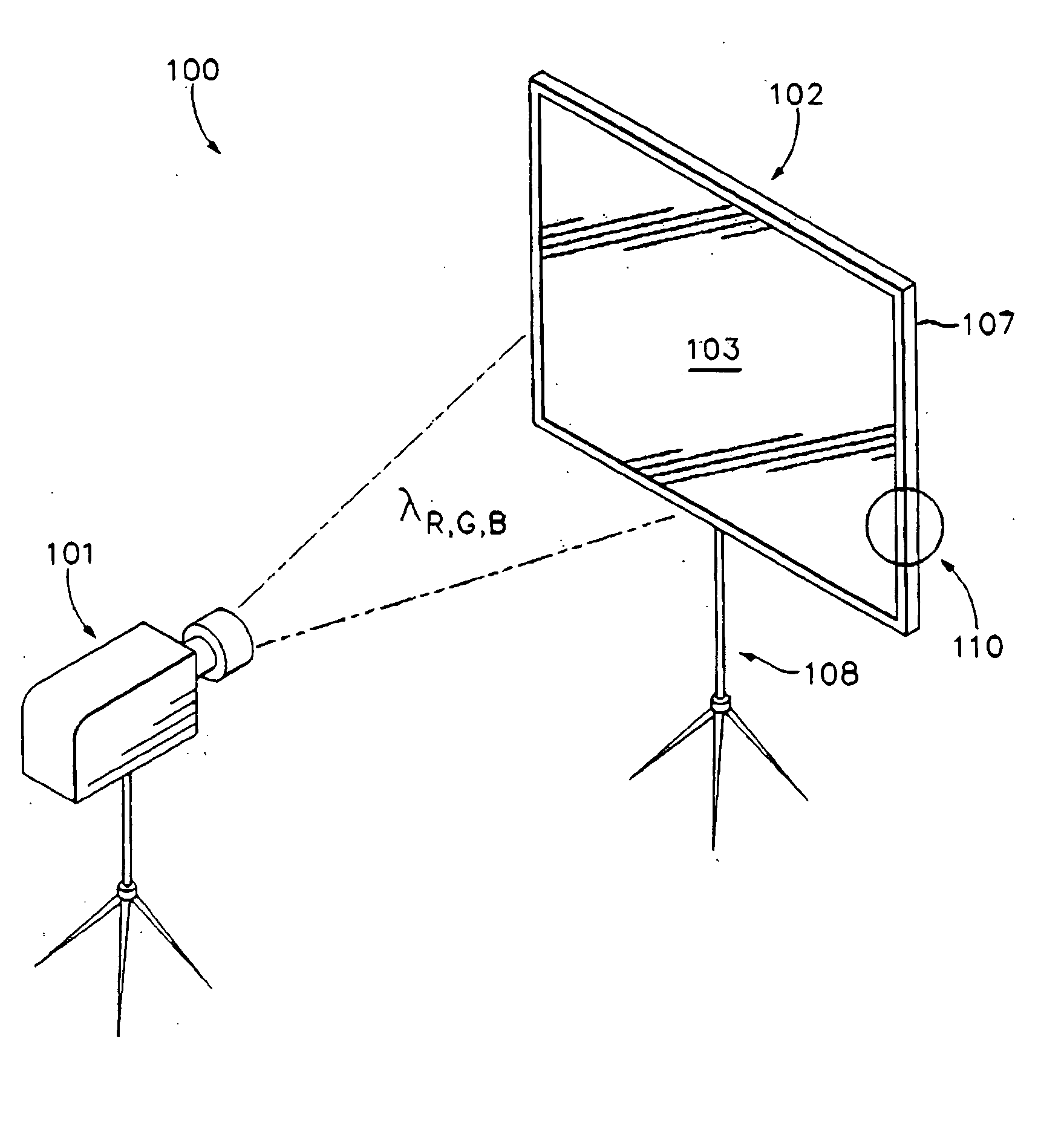
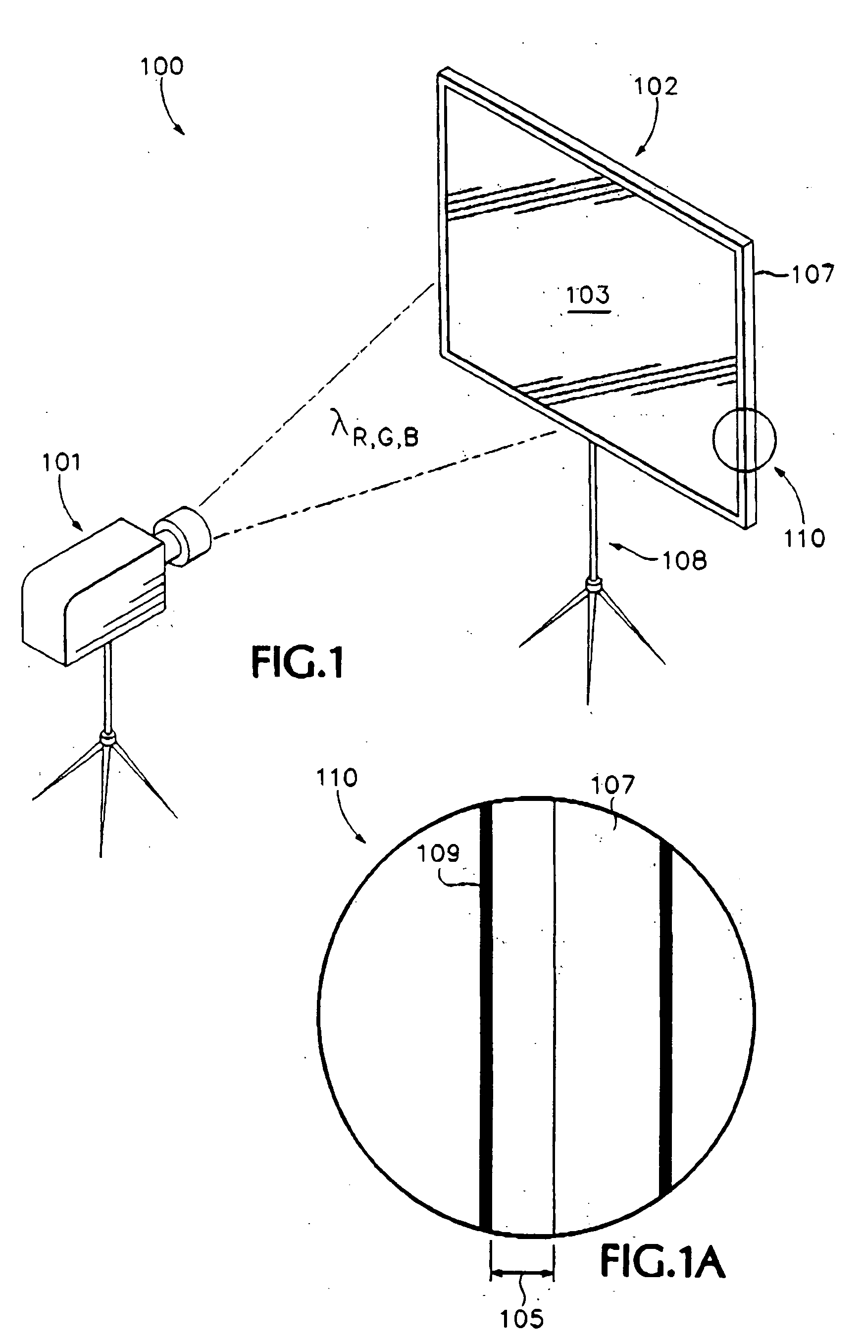
[0025]FIG. 1 is a perspective view, schematic illustration, showing a reflecting screen projection system 100. FIG. 1A is a magnified detail 110 of the reflective projection screen 102 of the system 100 as shown in FIG. 1.

[0026] Image and information projection apparatus, generically referred to as a “projector,”101 are known in the art. An exemplary red-green-blue, “RGB,” color projector 101 provides a projection, represented by a schematic, phantom-line, “beam region” labeled λR,G,B, onto a viewing screen 102 having a viewing surface region 103. The screen 102 has a support; or frame, 107 and a stand 108.

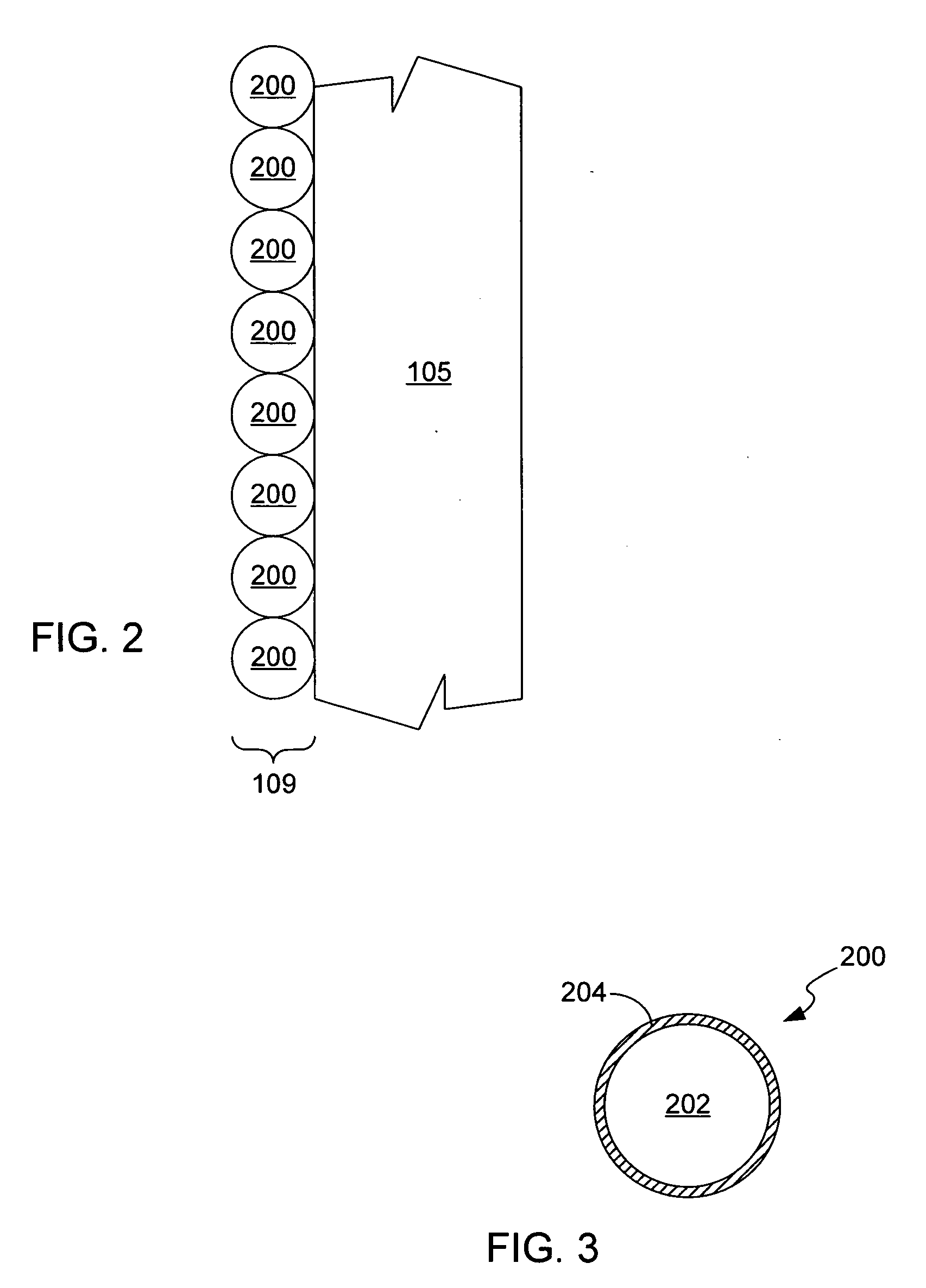
[0027] Looking also to FIG. 1A, the viewing surface region 103 includes a substrate 105 and a surface coating 109. The substrate 105 can be any material th...


PUM


Abstract

A reflector comprises a core and a first dielectric mirror formed over at least a portion of the core to reflect light having a preselected wavelength. The reflector may comprise a plurality of dielectric mirrors formed concentrically over the first dielectric mirror to reflect light having the preselected wavelength. The multiple dielectric mirrors may have different diffraction indices. A layer of such reflectors deposited onto the reflective surface of a projection screen may enhance the reflective selectivity of the screen to the preselected wavelength. Reflectors formed to reflect different wavelengths may be deposited onto the reflective surface to enhance selectivity to the different wavelengths and minimize reflection of ambient light.

Description

CROSS-REFERENCE TO RELATED APPLICATIONS [0001] This application is a continuation-in-part of U.S. Ser. No. 10 / 282,818, filed Oct. 28, 2002, the entire contents of which are incorporated herein by reference thereto.STATEMENT REGARDING FEDERALLY SPONSORED RESEARCH OR DEVELOPMENT [0002] Not applicable. REFERENCE TO AN APPENDIX [0003] Not applicable. BACKGROUND [0004] 1. Technical Field [0005] The invention relates generally to enhancing the reflection of selected light. [0006] 2. Description of Related Art [0007] Projection systems of both front projection, reflective viewing, and rear projection, transmissive viewing, are known in the art. A common problem in projection systems is that ambient lighting conditions reduce contrast and degrade viewing image quality. [0008] Typical projection technology focuses on hardware and electrical design of the projector to improve the color image quality of the projected image. A typical projector uses red, green and blue (“RGB”) filters in combin...

Claims


Application Information

Patent Timeline
Patent Type & Authority Applications(United States)
IPC IPC(8): G02B1/10G03B21/00G03B21/56
CPCG03B21/00
Inventor SAMUELS, BRIAN C.WANG, SHIH-YUANMAY, GREGORY J.WILLIAMS, STANLEY
Owner HEWLETT PACKARD DEV CO LP
Why Eureka
Try Eureka