Medium and apparatus for magnetic recording and method for measuring the offset amount

Inactive Publication Date: 2005-06-16
KK TOSHIBA
View PDF6 Cites 20 Cited by
  • Summary
  • Abstract
  • Description
  • Claims
  • Application Information

AI Technical Summary

Benefits of technology

[0013] It is an object of the present invention to at l

Problems solved by technology

However, in the case of the extremely high recording density more than 100 Gbit/in2, recording action into adjacent tracks occur

Method used


Image

  • Medium and apparatus for magnetic recording and method for measuring the offset amount
  • Medium and apparatus for magnetic recording and method for measuring the offset amount
  • Medium and apparatus for magnetic recording and method for measuring the offset amount

Examples


Example

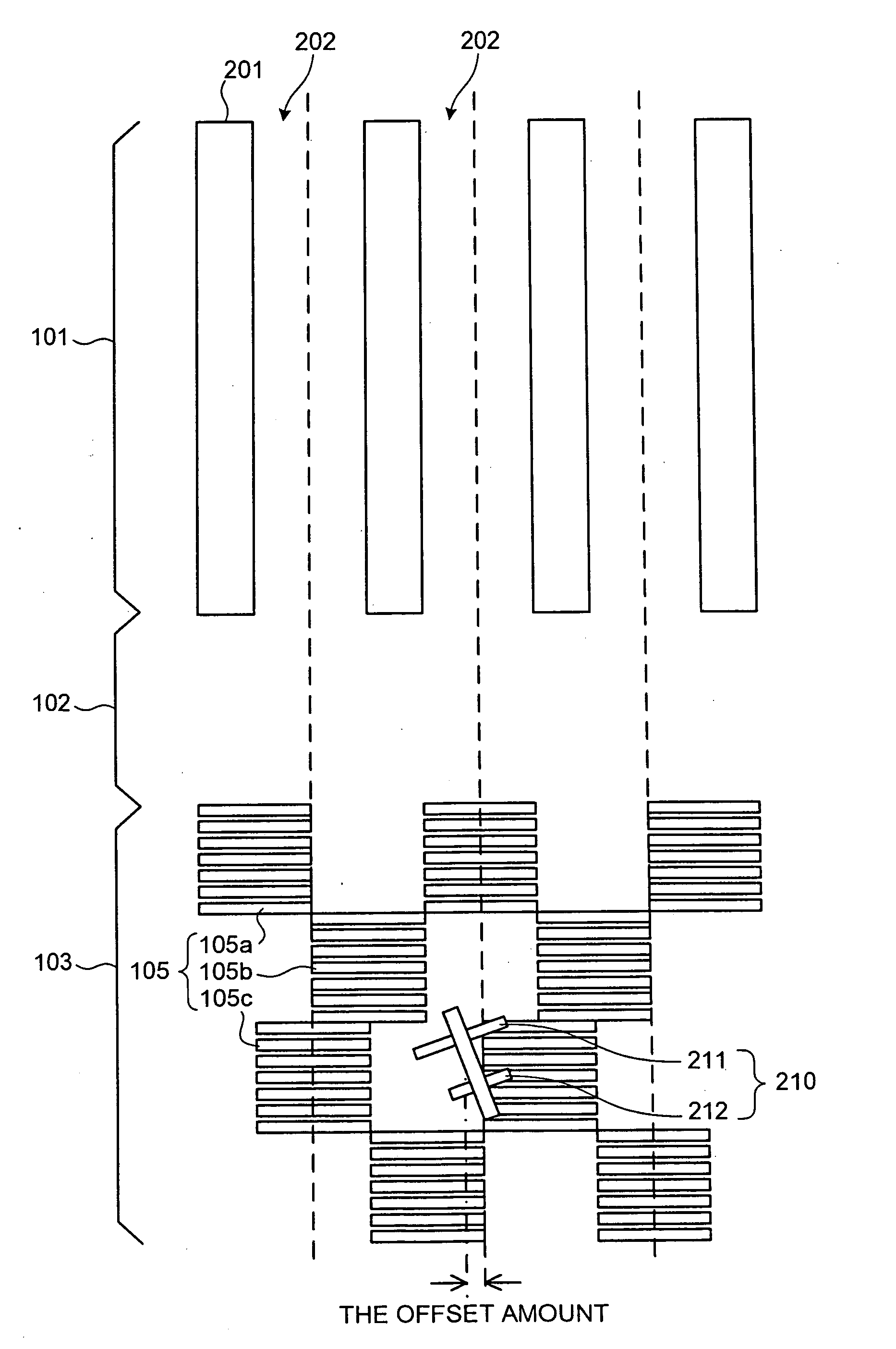
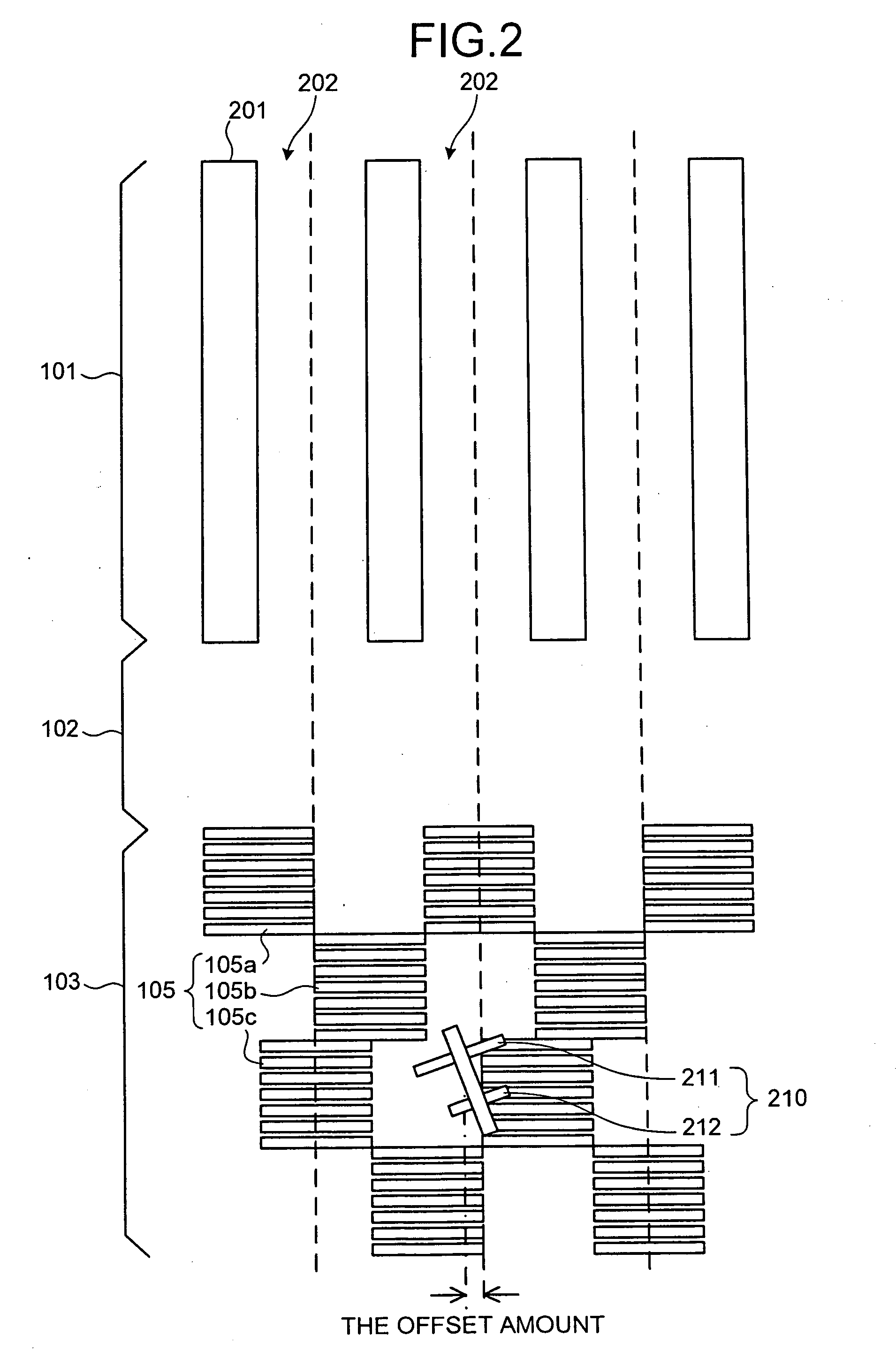
[0046] A structure of the hard disk of the first embodiment will be first described.

[0047] While the hard disk can be formed in any shape, the hard disk of the first embodiment is formed as a disk. The hard disk has a structure in which an offset amount measurement area is provided in a radial direction between the discrete area and the servo area. In the offset amount measurement area, the offset amount that is of a relative distance between the reproducing head and the recording head in a recording medium radial direction is measured.

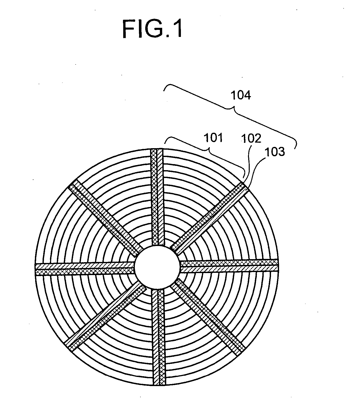
[0048]FIG. 1 is a schematic diagram that depicts the structure of the hard disk according to the first embodiment. The hard disk of the first embodiment is the discrete track type of hard disk that a composite magnetic head having a first head (in this embodiment, a recording head of HDD) and a second head (in this embodiment, a reproducing head of HDD) can record data on and reproduce data from. The hard disk has a plurality of sectors 104. Each se...

Example

[0080] Then, the structure of the hard disk according to the second embodiment is explained.

[0081] In the hard disk of the second embodiment, the offset amount measurement areas are provided on the inner radius side and the outer radius side of the discrete area of the disk.

[0082]FIG. 12 is a schematic diagram that depicts the structure of the hard disk according to the second embodiment. The hard disk of the second embodiment is the discrete track type of hard disk having the non-magnetic track between the magnetic tracks. Each sector 104 includes the discrete area 101 and the servo area 103. An offset amount measurement area 1202b where the non-magnetic track does not exist is provided on the inner radius side of the discrete area 101 of the innermost radius, and an offset amount measurement area 1202a is provided on the outer radius side of the discrete area 101 of the outermost radius. (In the case that the hard disk is formed in another shape other than disk, the offset amoun...

Example

[0106] The structure of the hard disk according to the third embodiment is explained.

[0107] In the hard disks of the first embodiment and the second embodiment, the center position of the magnetic track coincides with the center position of the servo area in any sector. On the other hand, the hard disk according to the third embodiment has both the sector in which the center position of the magnetic track coincides with the center position of the servo area and the sector in which the center position of the magnetic track differs from the center position of the servo area.

[0108]FIG. 20 is a schematic diagram that depicts the structure in each sector of the hard disk according to the third embodiment. As shown in FIG. 20, a discrete area 2000 includes the magnetic track 2002 made of the magnetic material in which the data can be recorded and the non-magnetic track 2001 in which the data can not be recorded. The non-magnetic track 2001 is provided between the magnetic tracks 2002. I...


PUM


Abstract

A magnetic recording medium includes a discrete area and an offset amount measurement area. The discrete area has a plurality of magnetic tracks where data can be recorded and that has a non-magnetic track where the data cannot be recorded located between the plurality of adjacent magnetic tracks. In the offset amount measurement area, measurement data for measuring an offset amount indicating a relative distance from a center position of the magnetic track to the first head in a direction crossing the magnetic track when the second head is on the center position of the magnetic track can be recorded.

Description

CROSS-REFERENCE TO RELATED APPLICATIONS [0001] This application is based upon and claims the benefit of priority from the prior Japanese Patent Application No. 2003-400873, filed Nov. 28, 2003, the entire contents of which is incorporated herein by reference. BACKGROUND OF THE INVENTION [0002] 1) Field of the Invention [0003] The present invention relates to a technology for performing magnetic recording in a medium. [0004] 2) Description of the Related Art [0005] Recently, as a storage capacity of a computer is increased, the storage capacity of a magnetic recording apparatus such as a hard disk drive (HDD) tends to increase. To increase the storage capacity of the magnetic recording apparatus, it is necessary to perform the recording in higher density by making a finer column of recording magnetic domains in a magnetic recording layer, which is formed by a signal magnetic field generated from a magnetic head. A perpendicular magnetic recording method is generally known as the meth...

Claims


Application Information

Patent Timeline
IPC IPC(8): G11B5/00G11B5/012G11B5/016G11B5/65G11B5/02G11B5/09G11B5/596G11B5/82G11B21/02G11B21/10G11B27/36
CPCG11B5/012G11B2220/20G11B27/36G11B5/59627G11B5/02G11B5/016
Inventor NAKAMURA, HIROAKIYONEZAWA, MINORU
Owner KK TOSHIBA
Why Eureka
Try Eureka