Acoustic device and method for determining interface integrity

Inactive Publication Date: 2005-06-16
FUGRO CHANCE
View PDF28 Cites 18 Cited by
  • Summary
  • Abstract
  • Description
  • Claims
  • Application Information

AI Technical Summary

Benefits of technology

[0023] Another advantage of the present invention is that it is possible to generate historical baselines that provide analytical guidelines by mapping different case scenarios in a controlled situation, where the acoustic characteristics of areas of pipe that are void of backing, support, or frictional interface beyond the outside surface of the pipe wall would be mapped and used for analytical reference and comparative analysis.
[0024] Another advantage of the present invention includes that a strip-chart g

Problems solved by technology

Unfortunately, many times voids, cracks and fissures exist within the annulus area containing the cement.
The voids, cracks and fissures can countermine the whole purpose of the cement.
In fact, in some cases the voids, cracks and fissures can become a safety

Method used


Image

  • Acoustic device and method for determining interface integrity
  • Acoustic device and method for determining interface integrity
  • Acoustic device and method for determining interface integrity

Examples


Embodiment Construction

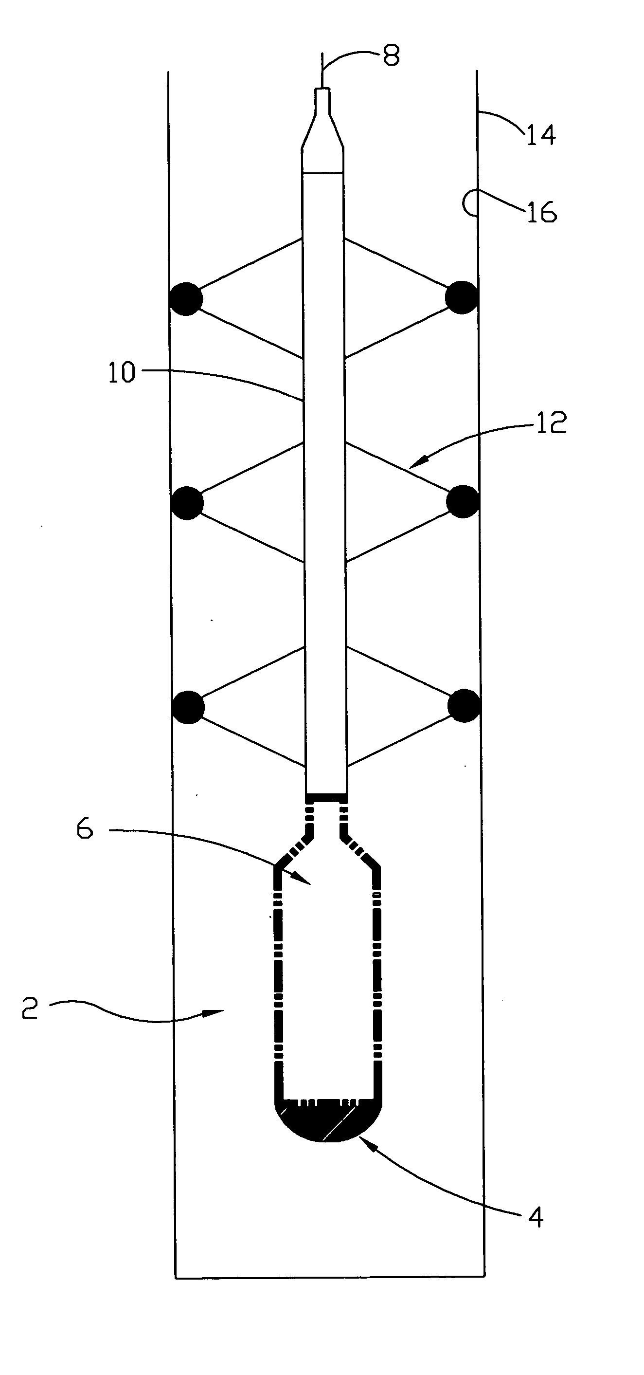
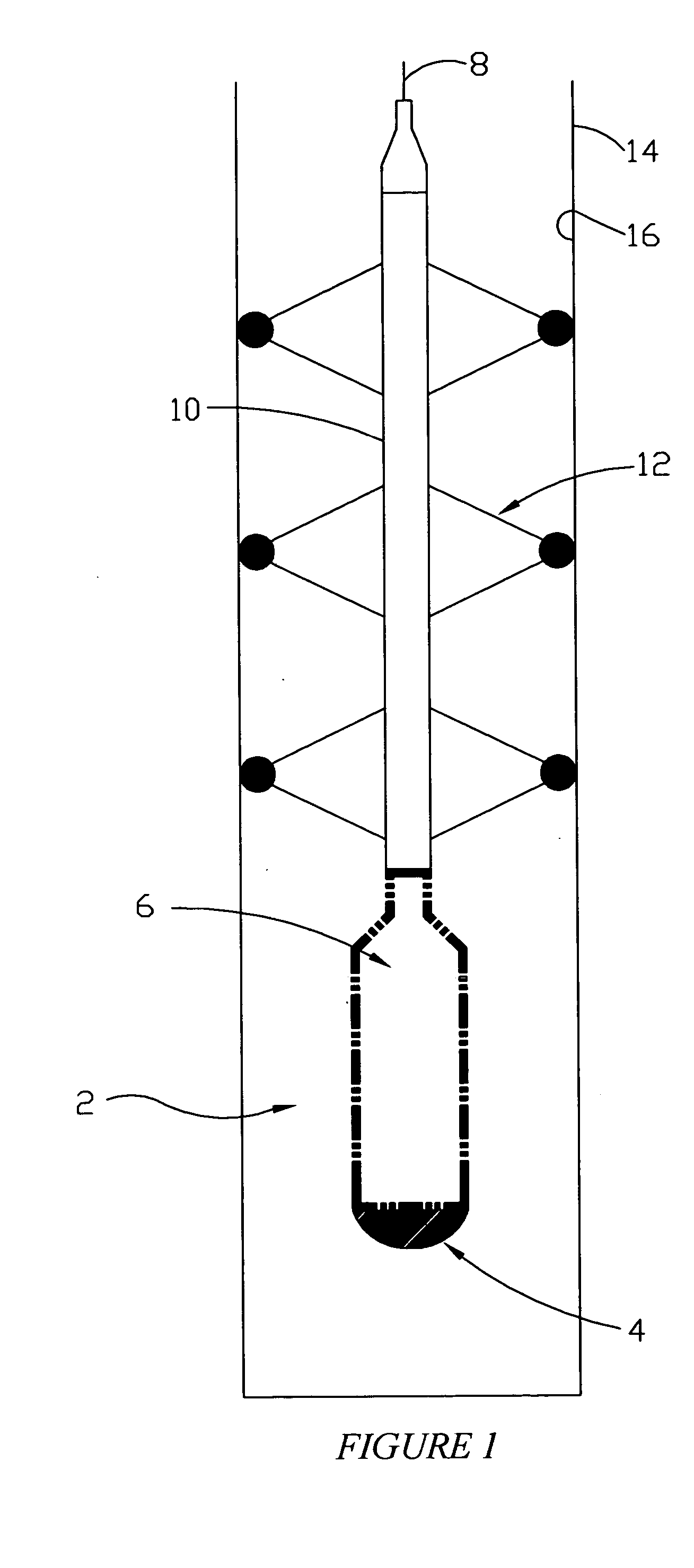
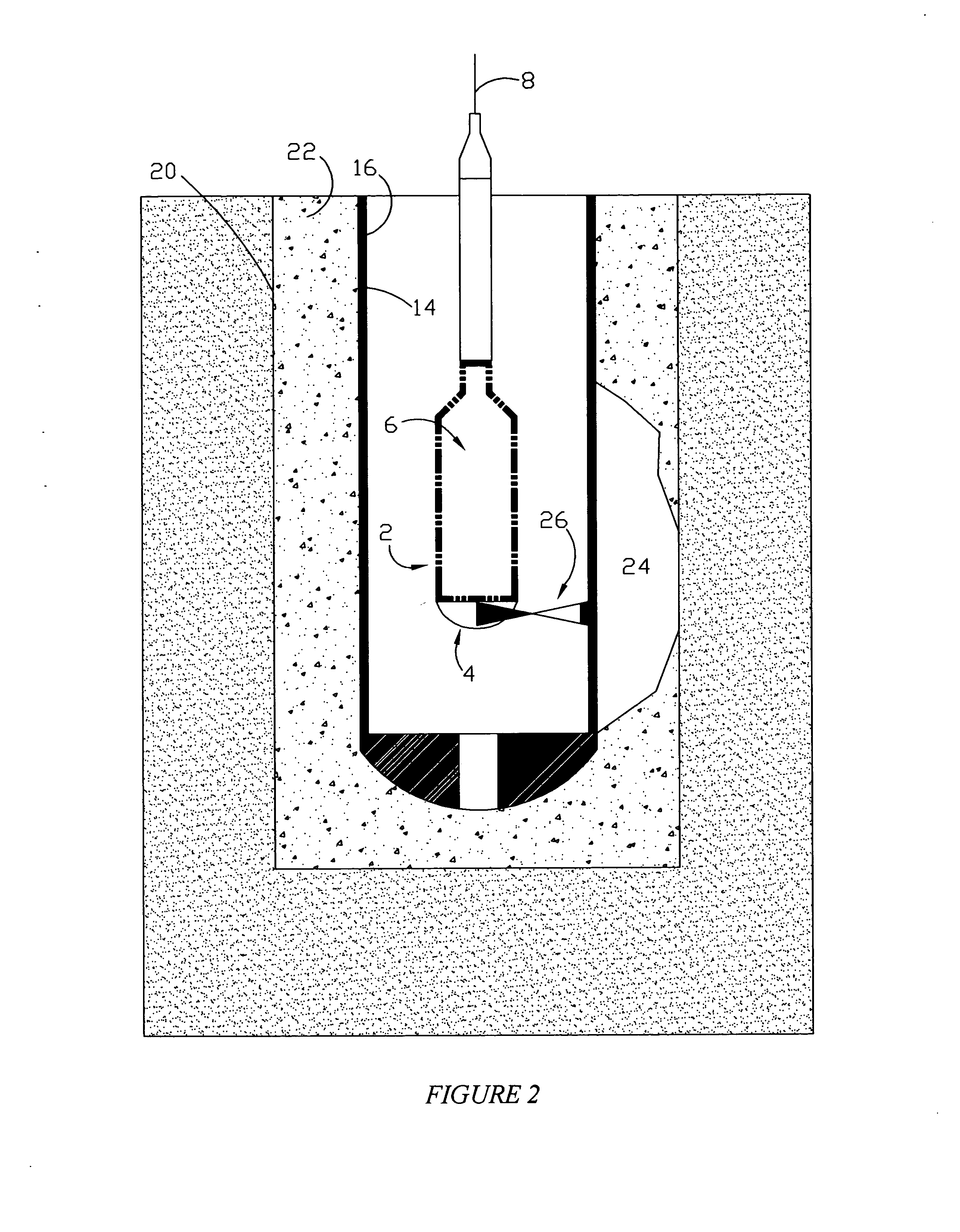
[0038] Referring to FIG. 1, a schematic view of the preferred embodiment of the tool of the present invention will now be described. The invention herein described utilizes a scanning sonar sensor and imaging device 2 for use in large diameter tubular inspection and tubular support analysis in earth penetration and uniform contact support situation.

[0039] In the preferred embodiment, the imaging device 2 consist of a scanning sonar transducer 4 that is a 360 degree sector scanning acoustic imaging tool. The sensor device 2 further comprises a sensor and acoustic signal processor 6 that is operatively attached to the scanning sonar transducer 4. The sonar sensor and imaging device 2 is commercially available from Simrad Inc. under the name Digital Mechanically scanned sonar Model # 974-2104. The device 2 further includes a data uplink means 8 for telemetering the collected data to the surface, which in the preferred embodiment is an electric wireline 8. The device 2 is interfaced to...


PUM


Abstract

A method and system for acoustically logging a tubular for an interface with a material. The method includes having a tubular disposed within a bore hole with the material being disposed within the annulus. The method comprises producing a first acoustic ping from an acoustic sensor located in the tubular, and recording a plurality of sample readings. The method then includes establishing a first time gate defining a sample window that is inclusive of samples representing compressional wave reflections from the perpendicular incidence of the acoustic ping and first contact with the inner tubular wall, and recording the sample set defined by the first time gate. Next, the acoustic sensor is rotated and a second acoustic ping is produced. The method further comprises establishing a second time gate defining a sample window that is inclusive of samples representing compressional wave reflections from the perpendicular incidence of the acoustic ping and first contact with the inner tubular wall and recording the sample set defined by the second time gate.

Description

BACKGROUND OF THE INVENTION [0001] This invention relates to a method and system for determining the environmental interface integrity of a fluid filled tubular. More particularly, but not by way of limitation, this invention relates to the use of sonar sensor technology to determine the interface integrity of a tubular having cement material disposed about the tubular's outer diameter portion. [0002] In the drilling of oil and gas wells, operators find it necessary to place a tubular string within a second tubular string, or within a bore hole. In order to hold the tubular string in place, a material such as cement is placed within the annulus. The cement bonds to the outer diameter portion of the tubular so that the tubular is held in place. [0003] As understood by those of ordinary skill in the art, the bonded cement produces several beneficial effects. For instance, the tubular is held in place. Also, communication from one subterranean zone to another zone is prevented. Additio...

Claims


Application Information

Patent Timeline
IPC IPC(8): G01V1/40G01V1/48
CPCG01V1/48
Inventor LABRY, KENNETH J.
Owner FUGRO CHANCE
Why Eureka
Try Eureka