
Image display device

a display device and image technology, applied in the direction of electrical transducers, stereophonic arrangments, television systems, etc., can solve the problems of not being able to deliver high-quality sound reproduction, and achieve the effects of improving the low-frequency sound quality, stable reproduction sound quality, and reducing sound quality

Inactive Publication Date: 2005-06-16
SHARP KK
View PDF11 Cites 79 Cited by
  • Summary
  • Abstract
  • Description
  • Claims
  • Application Information

AI Technical Summary

Benefits of technology

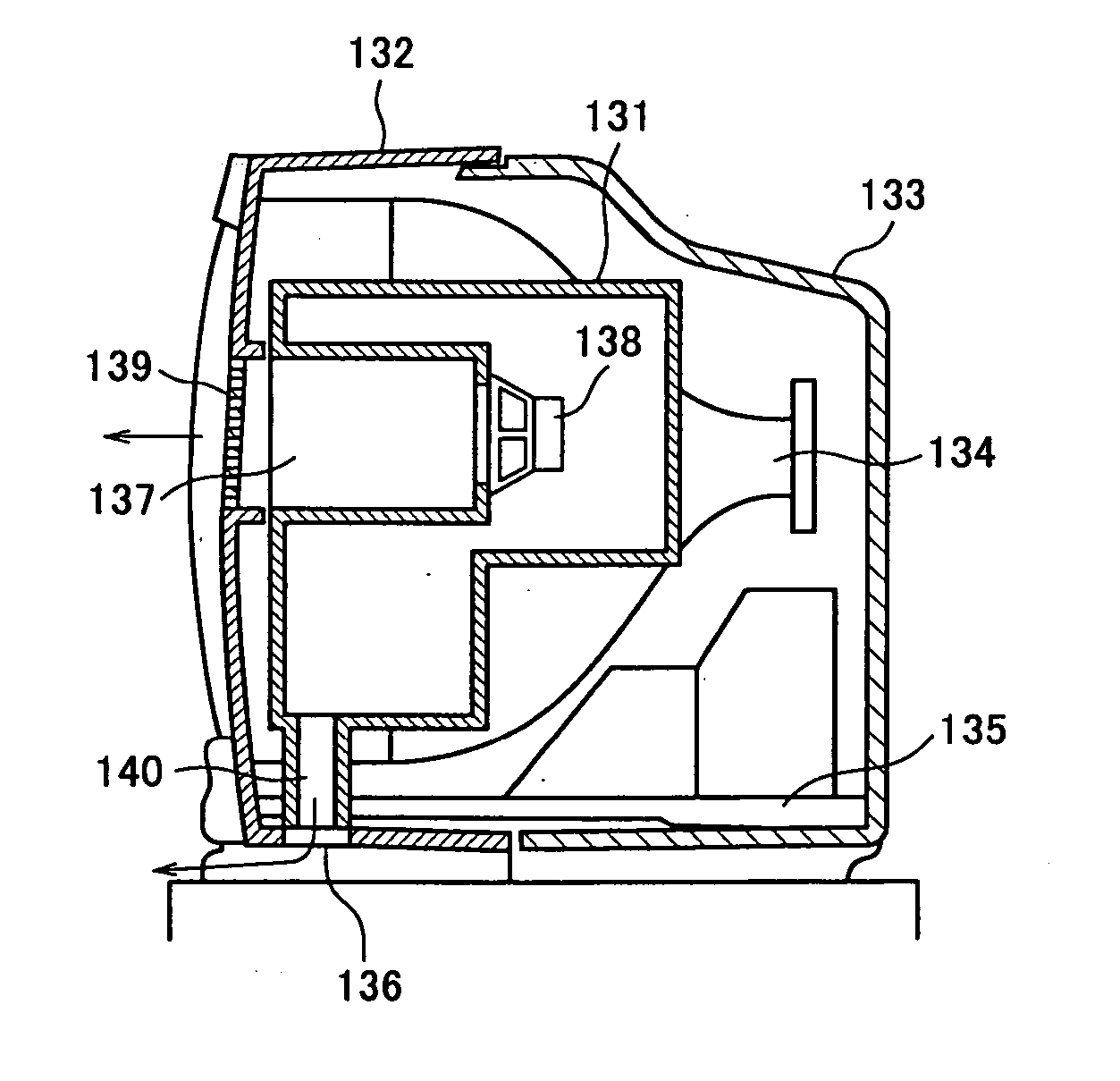
[0018] An object of the present invention is to provide an image display device which comprises a main body for displaying video on a display screen, a first loudspeaker for reproducing sounds of low frequency, a second pair of loudspeakers for reproducing sounds of middle and high frequency, a duct for improving the low-frequency sound quality of the first loudspeaker and a stand for supporting the display body, wherein the stand has a portion being opposite to the duct outlet. A cabinet housing the first loudspeaker and the second pair of loudspeakers has a plurality of through holes made in a first area substantially corresponding to an aperture of each loudspeaker and has a plurality of not-through (blind) holes within the second area around the first area, wherein the periphery of the second area for the first loudspeaker and the periphery of the second areas for the second pair of loudspeakers are different from each other in form and / or size. The above-described structure of the loudspeaker system can obtain the stable quality of reproduced sounds featured by the well-balanced reproduction of sounds of low, middle and high frequencies by the effect that the sounds from the first loudspeaker are absorbed by the bottom body of the stand and reflected from the same, eliminating the possibility of decreasing the sound quality by the affection of material of floor on which the television receiver is mounted.
[0019] Another object of the present invention is to provide an image display device which comprises a main body for displaying video on a display screen, a first loudspeaker for reproducing sounds of low frequency and a second pair of loudspeakers for reproducing sounds of middle and high frequency range, wherein a box housing therein the first and second loudspeakers has a plurality of through holes made in a first area substantially corresponding to an aperture of each of the loudspeakers and has a plurality of not-through (blind) holes within the second area around the first area, wherein the periphery of the second area for the first loudspeaker and the periphery of the second area for the second pair of loudspeakers are different from each other in form and / or size. The above-described design can realize the loudspeaker system being apparently larger than the actual size and attaining a sophisticated appearance of the article. The first and second loudspeakers arranged one on the both sides of the first loudspeaker can present the visually symmetrical, fine external design of the loudspeaker box while maintaining the mechanical strength thereof.
[0021] Furthermore, the above-described image display device may have a supporting stand on which the loudspeaker system is mounted in such a manner that the first loudspeaker is located between the second pair of loudspeakers. This can achieve a thinner design of a television receiver owing to separate mounting of the loudspeaker system on the stand.

Problems solved by technology

Because of the absence of a loudspeaker box, the television receiver has a small dynamic range of its sound system and therefore cannot deliver high quality sound reproduction.

Method used


Image

  • Image display device
  • Image display device
  • Image display device

Examples


Embodiment Construction

[0039] Preferred embodiments of the present invention will be described below with reference to accompanying drawings.

[0040]FIG. 5 shows a television receiver according to an embodiment of the present invention. FIG. 5(A) is a front view, FIG. 5(B) is a right-side view and FIG. 5(C) is a rear view of the television receiver. The television receiver 10 has a main display body 1 using a liquid crystal display (LCD) or a plasma display panel (PDP) and the like as a thin display unit 2, wherein the main body 1 is further provided at its front lower portion with a pair of left and right loudspeakers 4a, 4b for reproducing sounds of middle and high frequencies and a loudspeaker (woofer) 3 for reproducing sounds of low frequency placed between the pair of loudspeakers 4a and 4b .

[0041] A stand 8 is composed of a support 5, a base 6 and a handle unit 7. The stand 8 can be removably secured at its upper portion with machine screws 9 to the rear surface of the main display body 1. Thus, the...


PUM


Abstract

An image display device (10) has a main display body (1) provided with a thin display unit (2), a low-frequency loudspeaker (woofer) (3) and two middle and high frequency loudspeakers (tweeters) (4a, 4b) and a stand (8) supporting the main display body (1). The stand (8) has a base (6) being just opposite at its top surface to a duct outlet of the woofer (3) , thereby sound emitted from the duct can be constantly absorbed by and reflected from the base and provided with the stable quality without influence of the floor's material. A housing containing the first loudspeaker and a pair of the second loudspeakers has a plurality of through holes formed in a first area corresponding to an aperture of each loudspeaker (3, 4a, 4b) and a plurality of blind holes formed in a second area surrounding the first area, wherein the second area for the first loudspeaker is different in peripheral shape and / or size from the second area for each of the second pair of loudspeakers. The above arrangement can attain an improved sound field expanding effect by using one woofer and two tweeters, attaining the sophisticated design of the loudspeaker system.

Description

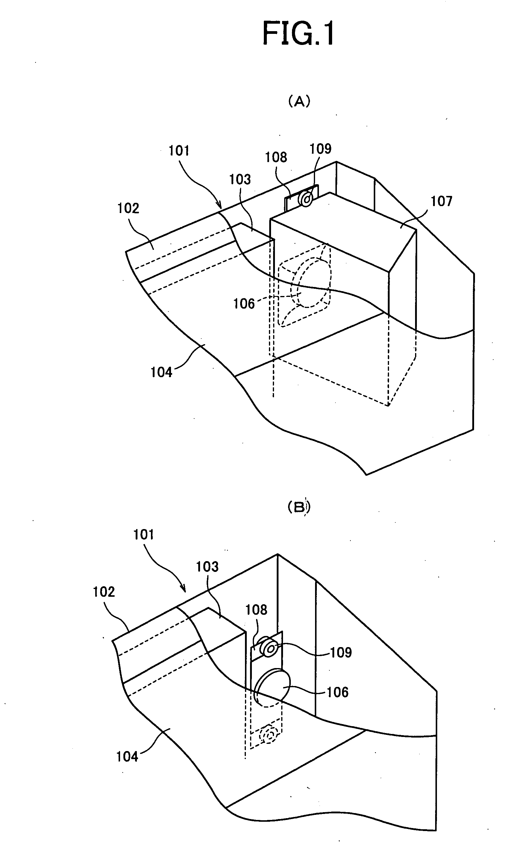
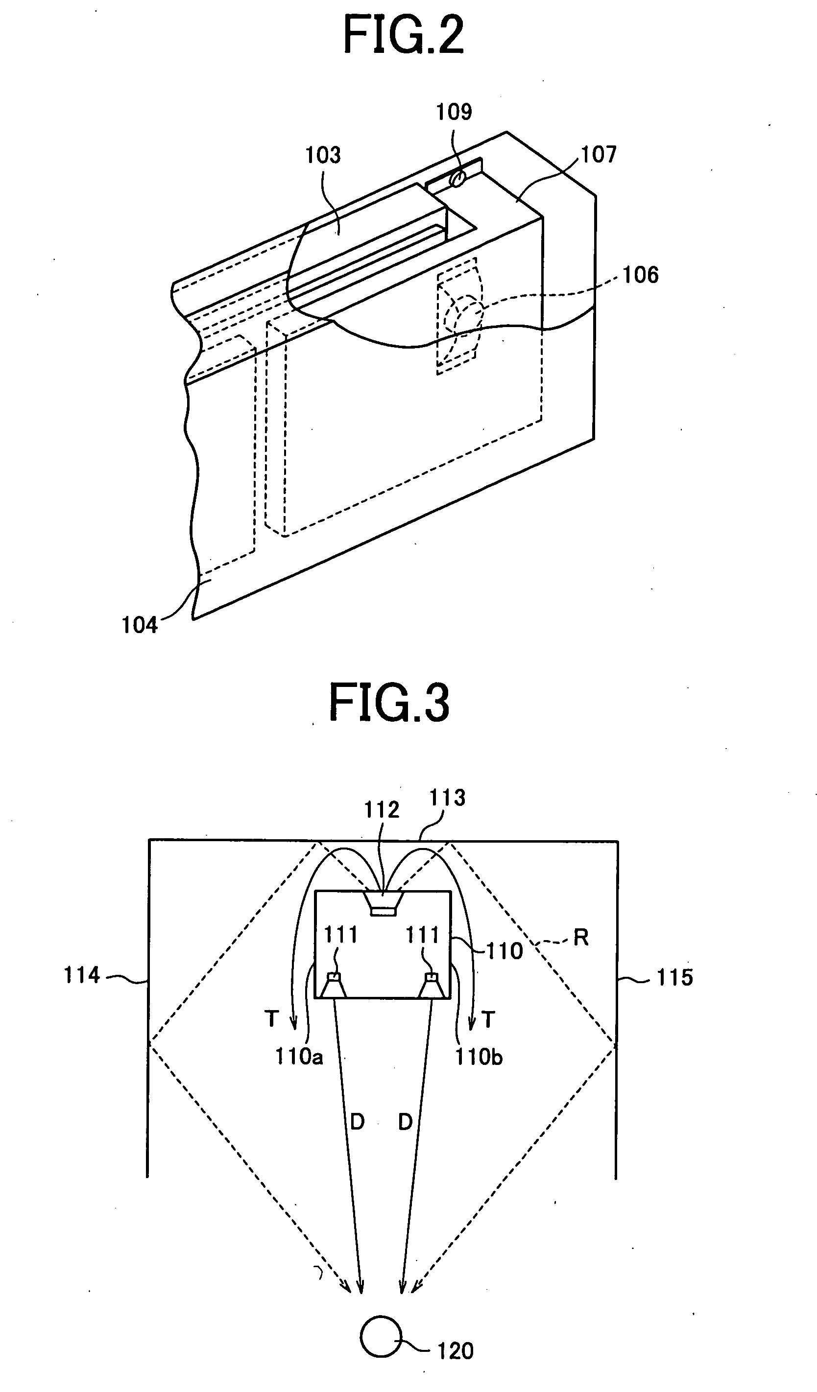
FIELD OF THE INVENTION [0001] The present invention relates generally to an image display device and, more specifically, to a personal computer equipped with a thin display such as a liquid crystal display (LCD) device and a plasma display panel (PDP) device or an image display device applicable to a display portion of a television receiver. BACKGROUND OF THE INVENTION [0002] In recent years, the production of small and thin electronic devices has been advanced with development of electronic technology and a growing consumers' demand for thinner and smaller home electronic apparatuses. Indeed, various kinds of television receivers are now available, which are constituted by using thin CRTs, LCD panels and plasma-display panels. The television receivers have video reproducing function and sound reproducing function. The latter function is realized generally by means of loudspeakers. [0003]FIGS. 1 and 2 illustrate a typical exemplary structure of a loudspeaker portion of a conventiona...

Claims


Application Information

Patent Timeline
IPC IPC(8): H04N5/64H04N5/66H04R1/26H04R1/28H04R5/02
CPCH04N5/642H04N5/66H04R2499/15H04R1/2857H04R5/02H04R1/26H04N5/64H04R1/00H04R1/02
Inventor TAMURA, ICHIROOHTSUKA, KOHJI
Owner SHARP KK
Learn More