
Vehicular optical communications system

a technology of optical communication system and vehicle, applied in the field of vehicle communication, can solve the problems of delay between the occurrence of road hazards, insufficient transmission of signals to vehicles, and insufficient safety of vehicles

Inactive Publication Date: 2005-06-16
CELEVATORON LABS
View PDF6 Cites 36 Cited by
  • Summary
  • Abstract
  • Description
  • Claims
  • Application Information

AI Technical Summary

Benefits of technology

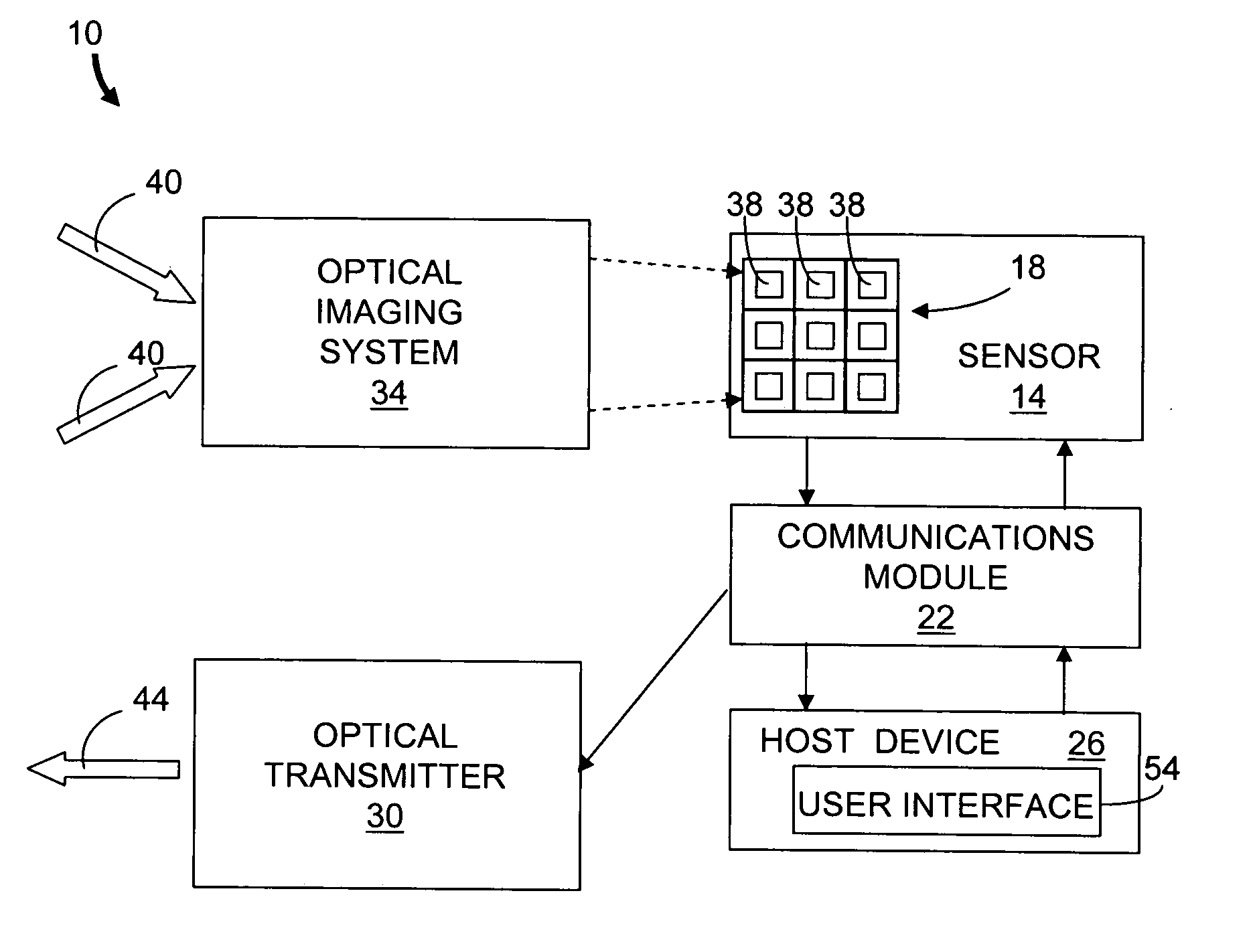
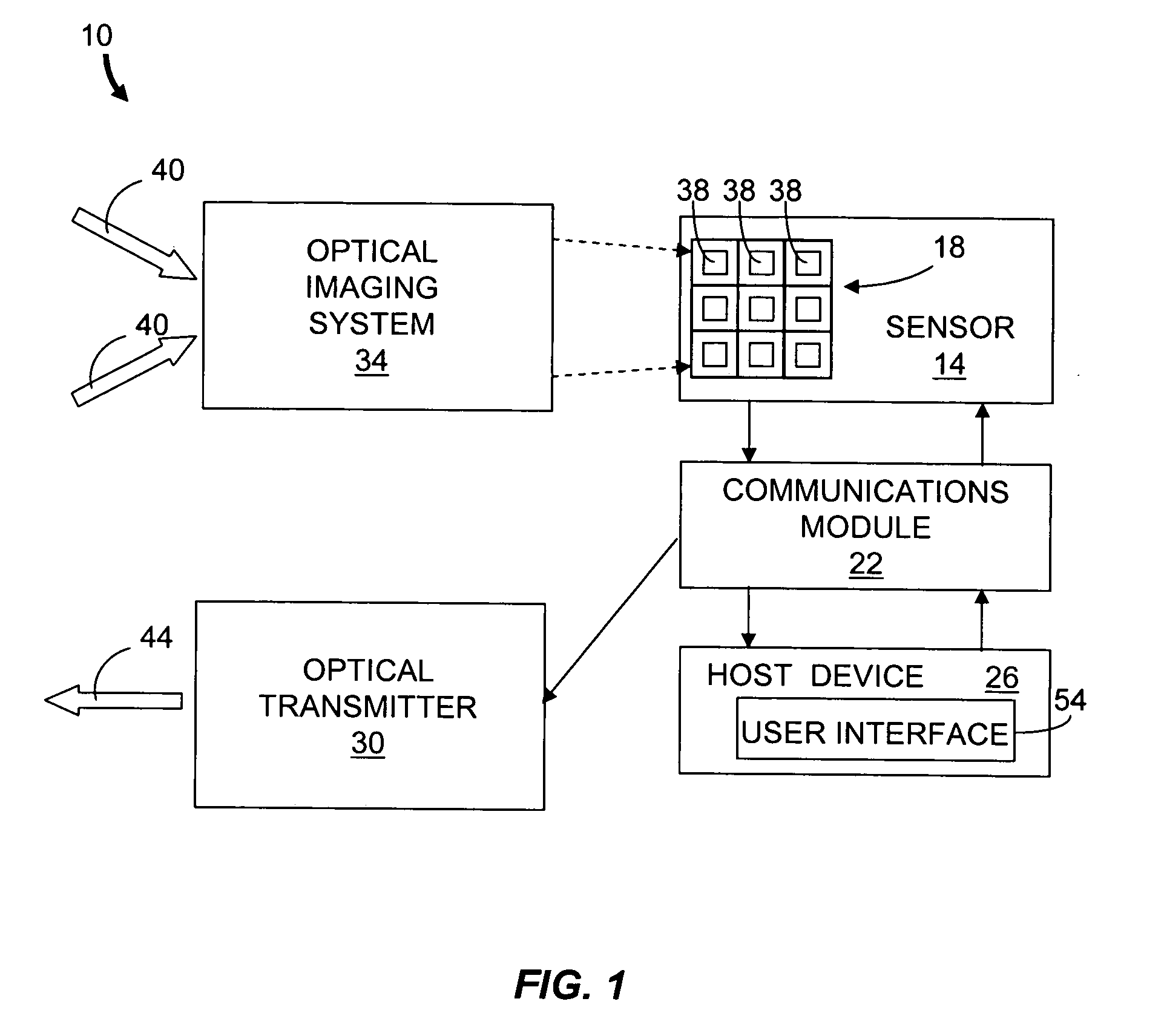
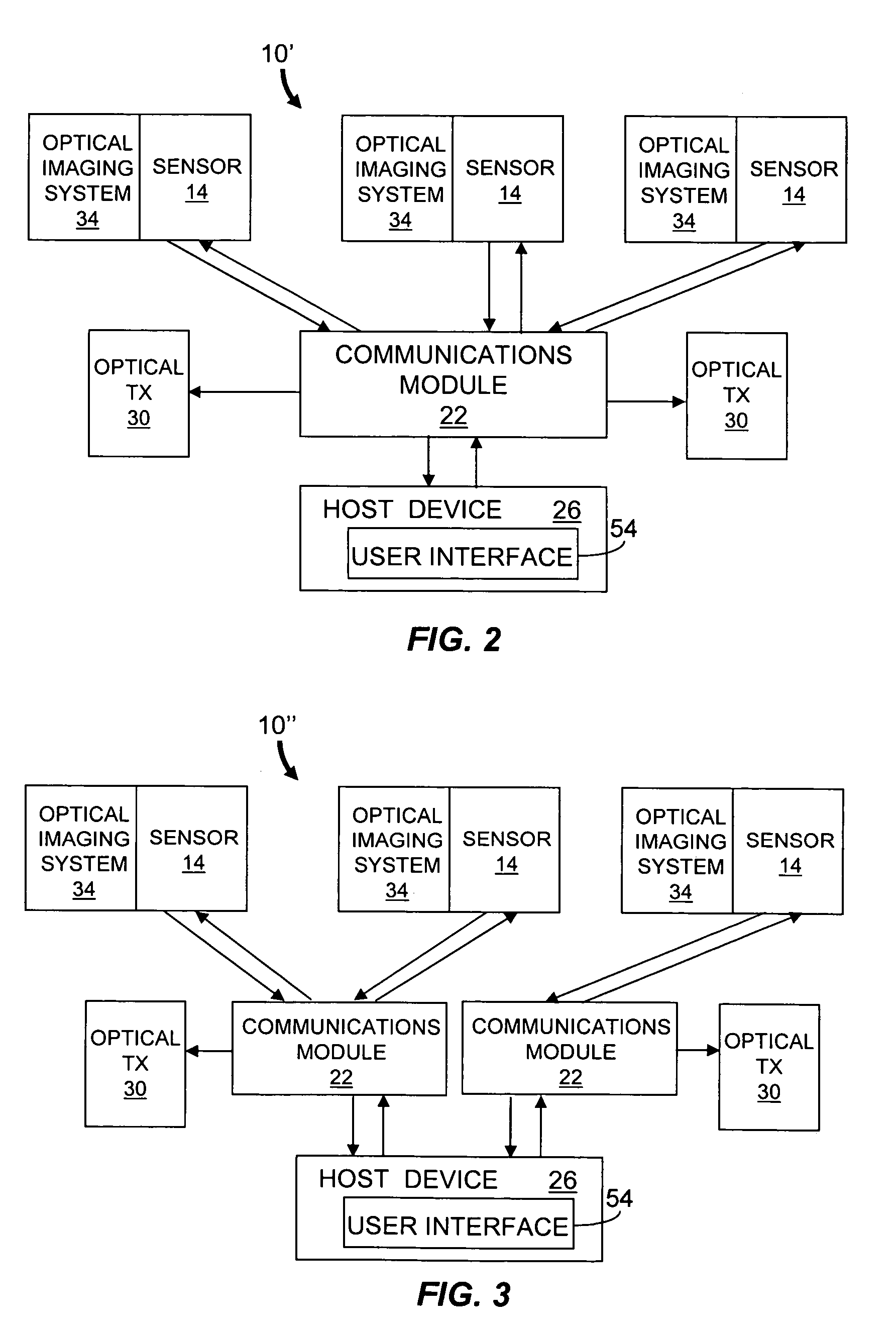
[0008] In one aspect, the invention features a vehicular optical communications system including a sensor and a communications module. The sensor has a plurality of pixels and detects an image in a field of view. Each pixel is configured to generate a pixel data signal in response to an optical data signal including vehicle data generated by a remote optical transmitter in a respective pixel field of view. The communica

Problems solved by technology

Unfortunately, such signs often do not relay sufficient information to vehicles to enable drivers to make informed decisions regarding alternate routes.
Moreover, there is a delay between the occurrence of a road hazard (e.g., traffic delay, construction, weather) and the update of the sign or traffic report.
Safety is another area that is restricted by the inability to rapidly convey vehicle information to a driver.
Thus drivers generally are not aware of the traffic hazard when the first affected vehicles apply their brakes.
Still another area limited by information transfer rates is general information such as advertisements for local businesses (e.g., restaurants and lodging).
Many such businesses may not advertise along the roadway or local zoning may prohibit their display of advertisement signs.
For businesses that do utilize roadside advertisements, the information is generally limited.
Advertisements often do not provide important information to passengers such as prices, hours of operation and product availability (e.g., hotel vacancy status).
Although such information is often available through the Internet, passengers typically do not have access to these Internet resources through their vehicles.
Trains, aircraft and other vehicles are similarly limited in their ability to receive information.

Method used


Image

  • Vehicular optical communications system
  • Vehicular optical communications system
  • Vehicular optical communications system

Examples


Embodiment Construction

[0023] In brief overview, the present invention features a vehicular communications system to exchange high bandwidth optical data between vehicles or between a vehicle and a stationary host. As used herein, vehicle means any conventional mobile host such as a car, bus, van, automobile, truck, aircraft and train. Other means of transportation such as humans carrying devices supporting optical communications are also contemplated as vehicles according to the principles of the invention. The vehicular communications system includes a communications module in communication with a sensor having an array of pixels. Each pixel is configured to generate a pixel data signal in response to an incident optical communication signal from a remote optical transmitter in the pixel's field of view. The communications module provides remote data in response to one or more pixel data signals generated by the sensor. The vehicular communications system optionally includes an optical transmitter to en...


PUM


Abstract

Described are a vehicle optical communications system and network to exchange high bandwidth optical data between vehicles or between a vehicle and a stationary host. The vehicle optical communications system includes a communications module and a sensor having pixels for detecting an image in a field of view. Each pixel can generate a pixel data signal responsive to an incident optical data signal that includes vehicle data transmitted from a remote optical transmitter. The communications module provides remote data in response to the pixel data signals. The vehicular communications system optionally includes an optical transmitter to enable bi-directional communication. Data can be transmitted through a multi-node network of vehicular communication systems deployed in vehicles or on stationary hosts located between or around the data transmitter and intended data receiver. Simultaneous data from multiple optical transmitters within the sensor field of view are processed concurrently and maintained as separate communication channels.

Description

RELATED APPLICATIONS [0001] This application claims the benefit of the filing date of co-pending U.S. Provisional Application Ser. No. 60 / 529,431, filed Dec. 12, 2003, titled “Communication Imagers for Automotive Safety Applications,” the entirety of which provisional application is incorporated by reference herein.FIELD OF THE INVENTION [0002] The invention relates generally to vehicular communications. More particularly, the invention relates to optical communications between moving vehicles and optical communications between a moving vehicle and a stationary host. BACKGROUND [0003] Providing information to vehicles such as automobiles traveling on highways and other roads is typically accomplished using roadside signs, radio traffic reports and the like. Conventional roadside signs convey static information. Other roadside signs display dynamic information such as near real time reporting of traffic delays. Unfortunately, such signs often do not relay sufficient information to ve...

Claims


Application Information

Patent Timeline
IPC IPC(8): H04B10/00H04B10/22
CPCH04B10/22H04B10/1143
Inventor WILSEY, PHILIP A.MARTIN, DALE K.DIECKMAN, DARRYL S.BEYETTE, FRED R. JR.
Owner CELEVATORON LABS
Learn More