Two-part snap-together panel fastener

a panel fastener and snap-together technology, applied in the direction of threaded fasteners, screws, couplings, etc., can solve the problems of panel being subjected to manufacturing environments, delicate structures which cannot be easily damaged, and not desirable,

Inactive Publication Date: 2005-06-16
PEM MANAGEMENT INC
View PDF48 Cites 40 Cited by
  • Summary
  • Abstract
  • Description
  • Claims
  • Application Information

AI Technical Summary

Benefits of technology

[0008] More specifically, the applicant has invented a captive panel fastener assembly comprising a screw having an enlarged head, a shank, and a threaded portion of greater diameter than the shank. The fastener includes a retainer having a flange at the top, a bore receiving the screw, and a plurality of axially-extending resilient fingers at the bottom, the fingers each include an outward-facing barb and an inward-facing fingertip adjacent the shank when assembled. The diametric distance between the fingertips at rest is less than the diameter of the threaded portion of the screw but greater than the diameter of the shank. Spring means is operative between the screw head and the retainer flange to bias the screw in a retracted position. A ferrule includes a bore with an internal annular flange dimensioned to cooperate with the resilient retainer fingers by snap action whereby the barbs are forceably engaged with the internal flange to join the ferrule and the retainer. The ferrule further includes panel attachment means adjacent a bottom end and a second radially extending outer flange proximate the bottom end thereof. When applied, snap fingers and a solder joint rigidly attaches the ferrule to an aperture in the circuit board panel. The ferrule further includes a barrel portion located between the retainer flange and the second outer flange proximate the bottom end thereof. The fastener may also include a device that is captivated by the retainer flange and the ferrule outer flange whereby the device is attached to the panel. In one embodiment, the device is a lever rotatable about an outside surface of the barrel of the ferrule. Preferably, the retainer also includes a bottom-facing bevel on the inside surface of each fingertip. This provides a locking function since the threaded portion of the screw includes a downwardly-angled top land which engages the bevel upon upward retraction of the screw from the ferrule. Thus, if the screw is pulled away from the panel, the retainer fingers are forced outwardly against the internal flange of the ferrule preventing further retraction. The screw sub-assembly can only be released from the ferrule by first pushing in the screw while pulling on the retainer. Since this operation requires the application of forces to different parts of the assembly in different directions, inadvertent removal of the spring sub-assembly from the ferrule is avoided.

Problems solved by technology

A problem exists, however, because this may not be desirable.
The panel may be subjected to manufacturing environments such as excessive heat that is not compatible with the materials of the screw / spring assembly.
By nature, the screw / spring sub-assembly of these fasteners includes more delicate structures which cannot survive many harsh manufacturing environments such as those experienced during circuit board manufacture.
However, there is a need to have the panel fastener attachment occur during or prior to manufacturing steps such as wave soldering.
Therefore, while a permanently assembled panel fastener has the advantage of the permanent retention of all components, it may not be suitable in all applications.

Method used


Image

  • Two-part snap-together panel fastener
  • Two-part snap-together panel fastener
  • Two-part snap-together panel fastener

Examples


Embodiment Construction

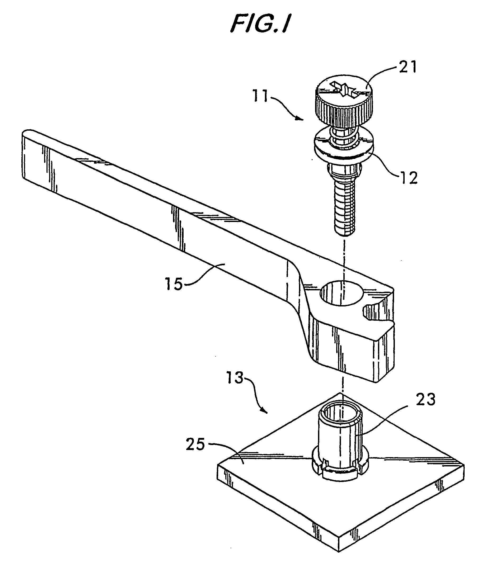
[0016] Referring now to FIG. 1, the present invention includes two major fastener sub-assemblies 11 and 13 snapped together to captivate lever 15 between cooperating flanges, one on each of the two inner fitting snap-together parts. The top part is a screw / spring sub-assembly 21 which includes a retainer 12 that snaps into the bore of the ferrule 23 that is pre-assembled to panel 25 in a separate assembly step. This sequence of assembly may take place as different events separated by time and distance as desired. For example, the assembly of the ferrule to the panel may take place during a wave-soldering process where it is not desirable to expose the other components to the heat and hazardous conditions in that manufacturing environment. As described further herein, the assembly of parts may support a rotatable element such as lever 15.

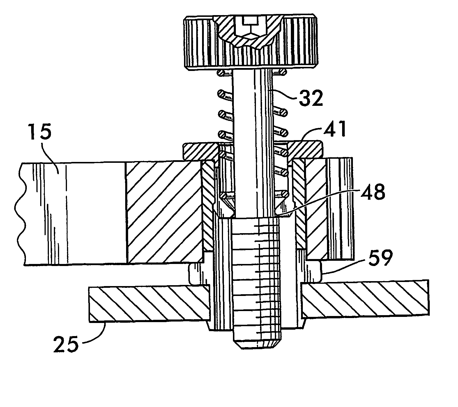
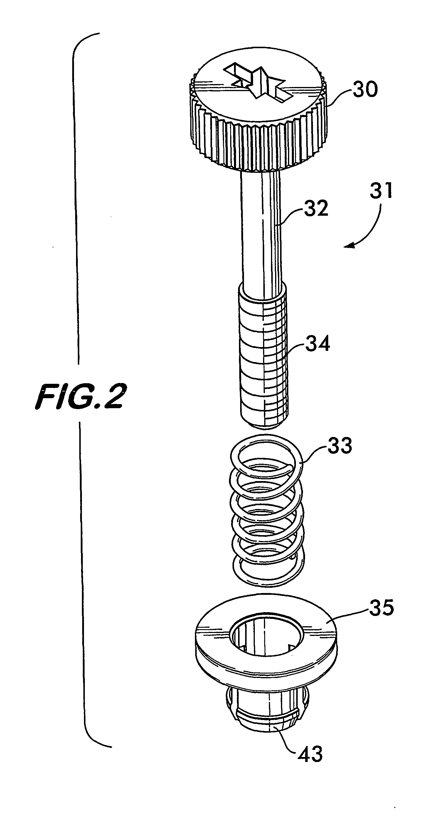
[0017] Referring now to FIGS. 2 and 3, an assembly view of the screw / spring sub-assembly is shown with screw 31 fitted inside of spring 33 and both...


PUM


Abstract

A two-part, snap-together captive panel fastener includes a ferrule portion and a screw sub-assembly which are attachable by snap fit. A locking mechanism prevents the unintended separation of the two components. The two-part structure of the present invention permits the ferrule which is preferably composed of a very hard and durable metal to be first wave-soldered to a printed circuit board with other elements of the board. Later, the screw sub-assembly can be snapped into the circuit board-mounted ferrule away for the harsh wave-soldering environment. The ferrule and screw retainer may further include cooperating outer flanges which captivate a pivoting structure such as a lever so that the panel fastener may not only be used to secure the attached panel to a sub-structure but may also affix other hardware to the panel.

Description

[0001] The present application is related to provisional patent application Ser. No. 60 / 354,920 entitled “Two-Part Snap-Together Panel Fastener” filed on Feb. 11, 2002, priority from which is hereby claimed.FIELD OF THE INVENTION [0002] The present invention relates to captive panel fasteners of the type having a retractable screw which is captive and extendable within a ferrule that attaches to a first panel. In fasteners of this type, the screw is usually held in its extended position by a spring but when depressed may be threaded into a second panel thereby joining the two panels. BACKGROUND OF THE INVENTION AND PRIOR ART [0003] Panel fasteners are well known in the art and include different means of attaching the ferrule to the first panel. Both snap-in and clinch-fit means of attachment are employed. The screw may be captivated in the ferrule by different means, but the captivation means are usually permanent and thus the screw and spring assembly is not detachable once the ass...

Claims


Application Information

Patent Timeline
Patent Type & Authority Applications(United States)
IPC IPC(8): F16B19/10F16B5/02F16B5/06F16B19/00F16B21/02F16D1/00
CPCY10T403/75F16B5/0208F16B19/00F16B21/18F16B39/00
Inventor BRUNO, DAVID J
Owner PEM MANAGEMENT INC
Why Eureka
Try Eureka