
Control apparatus for use with a computer or video game system

a control device and video game technology, applied in the field of control devices for use with a computer system, can solve the problems of reducing the realism of video games, affecting the playability of video games, and requiring multiple input devices

Active Publication Date: 2005-06-16
720 DEGREES
View PDF9 Cites 170 Cited by
  • Summary
  • Abstract
  • Description
  • Claims
  • Application Information

AI Technical Summary

Benefits of technology

[0023] The step of receiving information from the x-axis sensor may include connecting a vertical shaft to the y-axis sensor such that the vertical shaft rotates as the barrel is tilted left and right, connecting a second optical encoder disk attached to the vertical shaft such that the second optical disk rotates with the vertical shaft and providing at least one second optical encoder adapted to correlate the rotation of the second optical disk to a horizontal tilt of the barrel to provide information indicating a desired horizontal point of view of a user in the video game.

Problems solved by technology

While these traditional input devices are familiar to most users and easy to operate, they tend to take away from the realism of the video game.
As a result, these traditional control devices lack the functionality to provide for the control of these additional functions and features.
For example, it is quite common for users to utilize a computer mouse along with extensive use of the keyboard to input commands and perform actions in the video game because the computer mouse alone simply lacks sufficient functionality for today's video games.
The use of multiple input devices complicates the playing of these video games to the point where the user must spend a significant amount of time simply familiarizing himself with the control devices prior to even attempting to proceed with playing the game.
Naturally, this robs the user of both a sense of reality while playing the game and takes away from the user's enjoyment.
However, the mouse requires a large, flat and substantially smooth two dimensional surface over which the mouse moves and thus, the user is somewhat restricted in where he or she can use the mouse while still maintaining good control over positioning of the cursor.
While trackballs eliminate the need for a large flat surface, they are typically mounted on the keyboard or some other computer system component, which tends to limit where the user can utilize the trackball as well.
In addition, as noted above, both the computer mouse and trackball lack the functionality required to utilize the additional features and options available in advanced video games, thus necessitating the use of additional control or input devices and complicating video game play.
However, many do not add to realism in many other video games.
While some joysticks may include additional control inputs, and thus, provide for increased functionality, even these joysticks do not provide sufficient functionality to satisfy the requirements of advanced video games and typically require the contemporaneous use of the keyboard.
Thus, these devices are limited in that they rely on an array of receivers and have range limits.
In addition, they these control devices also lack functionality sufficient to play today's advanced video games.
While these devices allow a user more freedom in using the device, these devices do not make a video game experience any more realistic, as they tend to be substantially similar in size and shape to the traditional computer mouse and thus offer little realism.
Further, these devices function in a manner similar to the computer mouse and thus have similar limited functionality which means they are insufficient to control the additional options and features of today's advanced video games.
These devices do provide some more realism, however, they are only useful for targeting in the video game.
In addition, the user must point the light gun at the display in order to use it, which limits where the user can play the video game.

Method used


Image

  • Control apparatus for use with a computer or video game system
  • Control apparatus for use with a computer or video game system
  • Control apparatus for use with a computer or video game system

Examples


Embodiment Construction

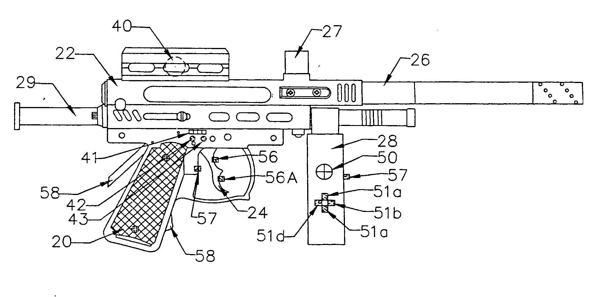
[0047] The control device 10 of the present application is particularly well suited for use by a player of a first person “shooter” type video game. In such video games, the player typically is presented with a first person view of an environment in the video game and is asked to aim at and shoot various targets. The user is commonly provided with a crosshair or other target designation, typically, in the center of the display. The point of view of the user in the game typically moves left, right, up, down, etc. based on the input from the computer mouse, keyboard, etc. to allow the user to aim at various targets in the video game. Targeting or aiming is typically accomplished by positioning the crosshair at the desired position, generally using the computer mouse or keyboard to change the point of view of the user in the video game or otherwise position the crosshair on the display in the video game. Shooting the target is typically accomplished by pressing a dedicated shoot button...


PUM


Abstract

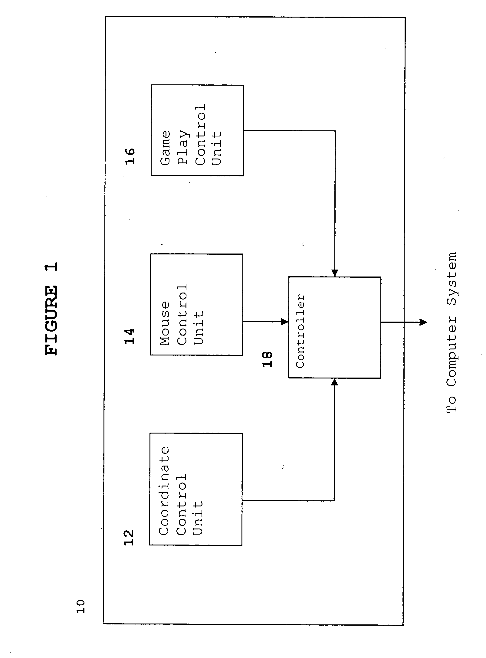
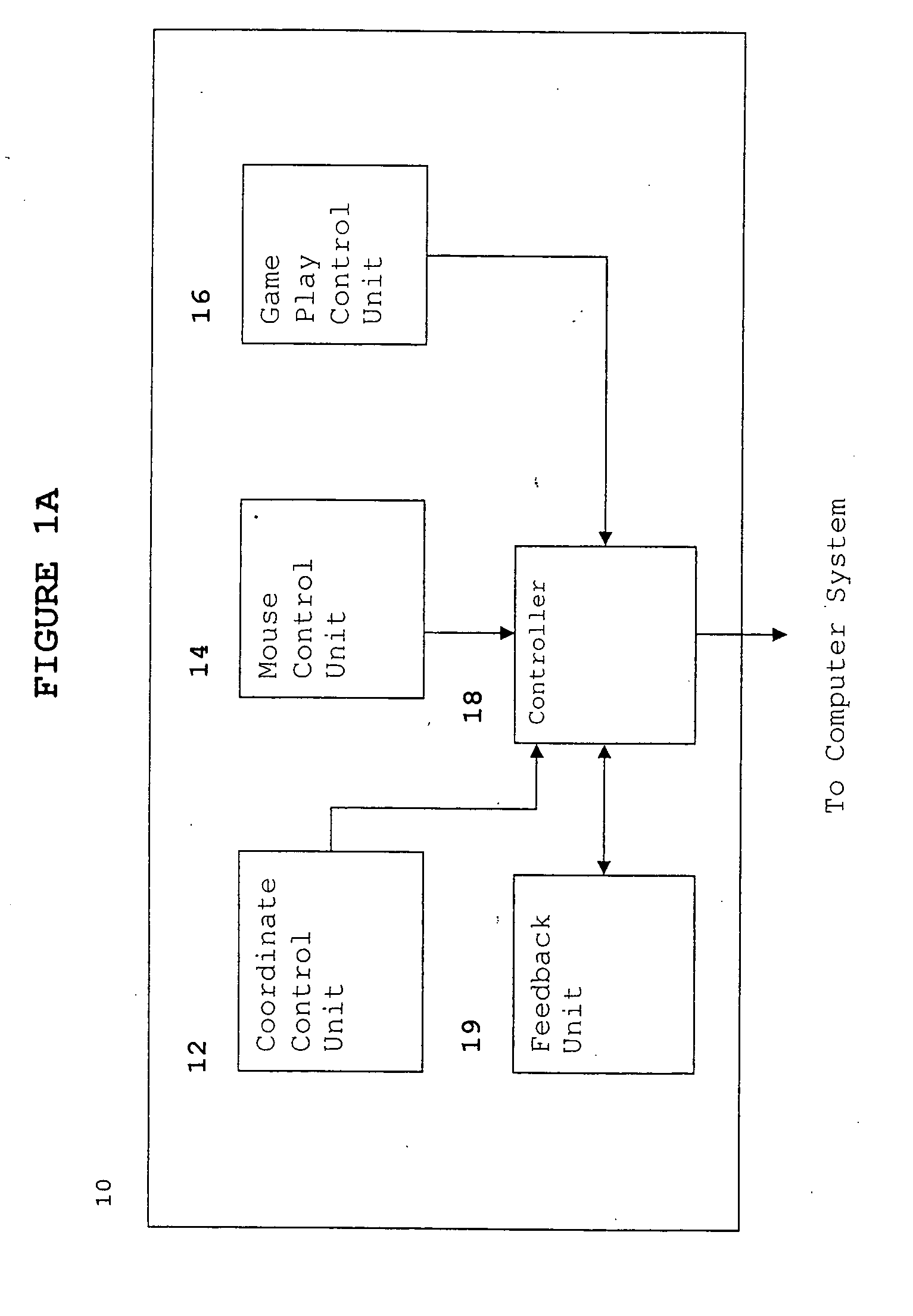
A control device for controlling a display of a computer system for use with a video game includes a coordinate control unit for providing information related to a vertical and horizontal tilt of the control device, a mouse control unit for inputting conventional mouse input information, a game control unit for inputting game control information and a controller for processing the information provided by the coordinate control unit, mouse control unit and game control unit. The vertical and horizontal point of view of the user in the video game and / or the vertical and horizontal position of a cursor on the display is determined based on the information related to the vertical and horizontal tilt of the control device. The control device is preferably shaped like a firearm to enhance the realism of the video game, but may be shaped like a conventional game pad.

Description

FIELD OF THE INVENTION [0001] The present application is related to a control device for use with a computer system. More specifically, the invention relates to a control device for controlling a display of the computer system based on the horizontal and vertical tilt of the control device for use with a video game. BACKGROUND OF THE INVENTION [0002] As computers have become a part of every day life, video games playable on computers have similarly become a very popular means of entertainment. While software and computer graphics innovations have made video games very realistic, most video games rely on more contemporary input devices such as a keyboard, computer mouse or joystick to allow a player to interact with the video game. While these traditional input devices are familiar to most users and easy to operate, they tend to take away from the realism of the video game. [0003] Furthermore, the improvements that have been made to video games have added many options and features th...

Claims


Application Information

Patent Timeline
Patent Type & Authority Applications(United States)
IPC IPC(8): A63FA63F13/00A63F13/06A63F13/219G06F3/033G06F3/0346
CPCA63F13/02A63F13/04A63F13/06A63F13/10A63F2300/1006F41A33/00A63F2300/105A63F2300/301A63F2300/308A63F2300/6676A63F2300/8076A63F2300/1043A63F13/837A63F2300/1037A63F13/533A63F13/219A63F13/285A63F2300/1062A63F13/5255A63F13/22A63F13/24A63F13/26A63F13/211A63F13/21A63F13/245
Inventor ARGENTAR, ERIC J.
Owner 720 DEGREES
Learn More