Chain with a mark
a technology of chain and mark, applied in the direction of driving chain, valve drive, gearing, etc., can solve the problems of increasing manufacturing cost, no guiding portion for the sprocket where the timing plate is located
- Summary
- Abstract
- Description
- Claims
- Application Information
AI Technical Summary
Benefits of technology
Problems solved by technology
Method used
Image

Examples
first embodiment
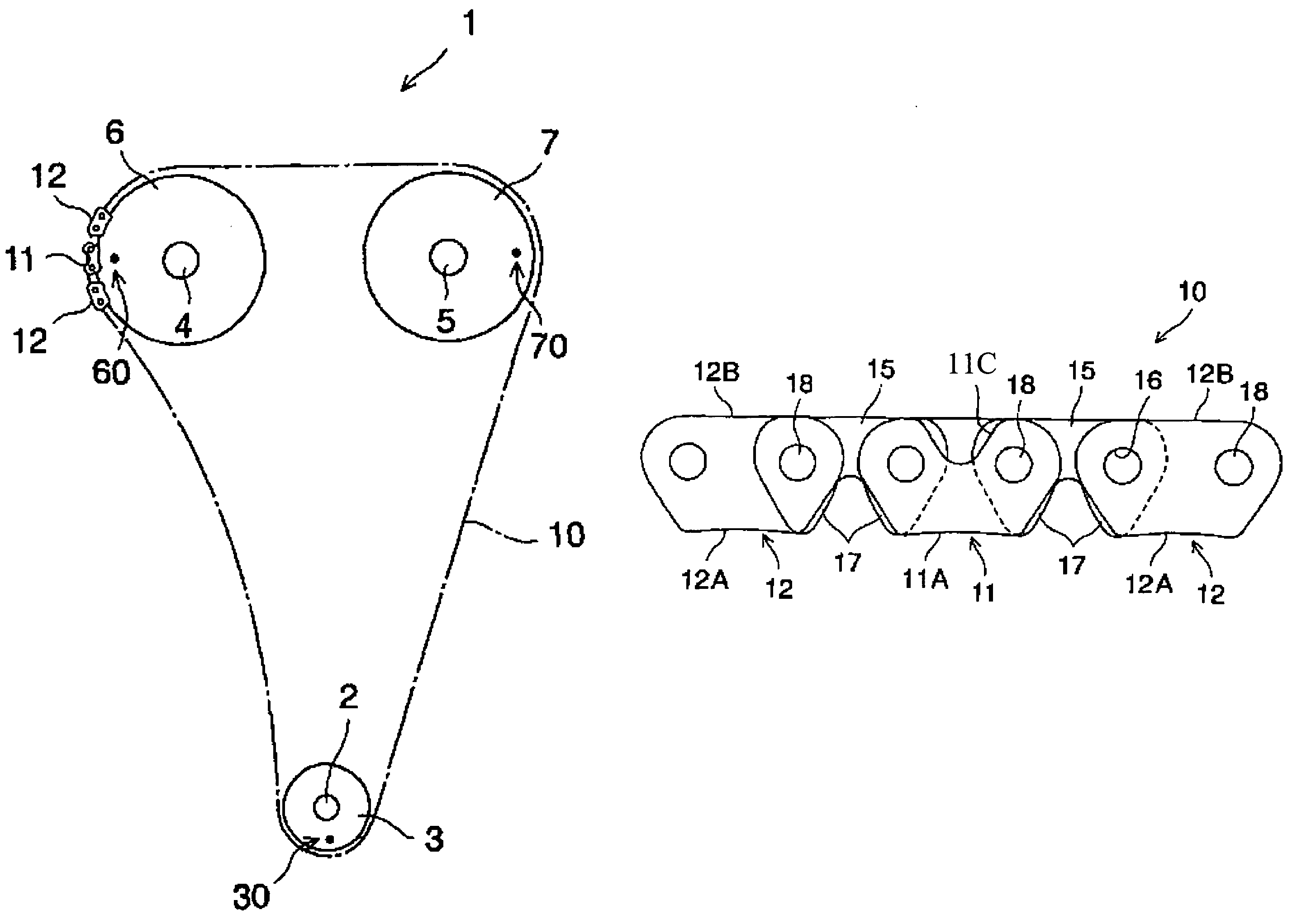
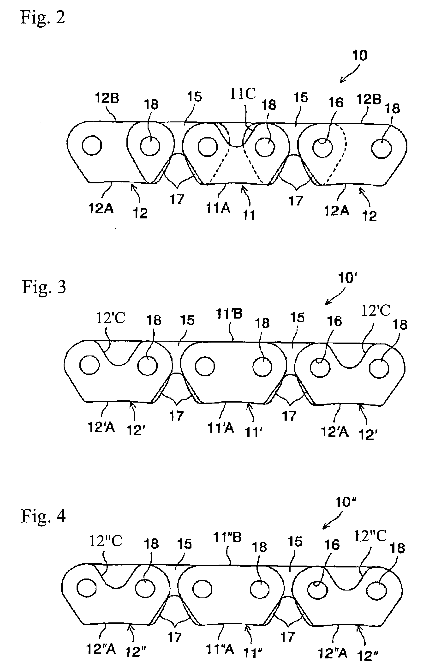
[0032]FIG. 2 shows a portion of the timing chain 10, which represents the present invention. As shown in FIG. 2, the timing chain 10 includes of a plurality of rows of interleaved link plates 15 each having a pair of pin apertures 16 and teeth 17 and pivotably connected to each other by connecting pins 18 inserted into the pin apertures 16. The timing chain 1 also has guide plates 11, 12 disposed outside the outermost link plates 15 and fixedly connected to the ends of the connecting pins 18.
[0033] Each of the guide plates 11, 12 has a flat portion 11A, 12A, respectively, on the engagement side with a sprocket. These flat portions 11A, 12A are disposed on opposite sides of the sprocket during engagement with the sprocket and maintain the chain centrally on the sprocket teeth.
[0034] The guide plate 11 has a crotch portion 11C on the backside of the plate opposite the engaging side. The bottom portion of the crotch 11C extends below the upper edges of the openings of the pin aperture...
third embodiment
[0041] Moreover, in the third embodiment, the guide plate 12″ has been pre-stressed but the guide plate 11″ has not been pre-stressed. That is, in this case, during assembly of the chain 10″, a pre-stress load or excessive tensile load is applied to the chain 10″ with the guide plates 12″ installed and the guide plate 11″ not installed. After pre-stress operation, the guide plate 11″ is installed into the chain 10″ to complete the entire chain.
[0042] According to the third embodiment, the guide plate 11″ is of relatively high rigidity without a crotch portion on the backside even though the plate has not been pre-stressed, whereas the other guide plate 12″ is of relatively low rigidity with a crotch portion on the backside that has been pre-stressed and subject to a residual compressive stress. As a result, the yield load of the guide plate 11″ or the timing plate can be made equal to that of the other guide plate 12″. In such a manner, the strength of the entire chain may be made u...
fifth embodiment
[0046]FIG. 6 shows a portion of the timing chain 110, which represents the present invention. As shown in FIG. 6, the timing chain 110 includes of a plurality of rows of interleaved link plates 115 each having a pair of pin apertures 116 and teeth 117 and pivotably connected to each other by connecting pins 118 inserted into the pin apertures 116. The timing chain 101 also has guide plates 111, 111′ disposed outside the outermost link plates 115 and fixedly connected to the ends of the connecting pins 118.
[0047] The guide plate 111 has a crotch portion 111C on the engaging side and a flat portion 111A on the backside opposite the engaging side. The bottom portion of the crotch 111C of the guide plate 111 extends below the bottom portion of the crotch portion of the link plate 115. Thereby, as shown in FIG. 7, a hatched portion g of the crotch portion 111C has a guiding function to locate the chain 110 centrally on the sprocket during engagement with the sprocket.
[0048] The guide pl...
PUM
 Abstract
Description
Claims
Application Information
 - R&D
- Intellectual Property
- Life Sciences
- Materials
- Tech Scout
- Unparalleled Data Quality
- Higher Quality Content
- 60% Fewer Hallucinations
Browse by: Latest US Patents, China's latest patents, Technical Efficacy Thesaurus, Application Domain, Technology Topic, Popular Technical Reports.
© 2025 PatSnap. All rights reserved.Legal|Privacy policy|Modern Slavery Act Transparency Statement|Sitemap|About US| Contact US: help@patsnap.com