Balloon catheter tip design

a catheter tip and balloon technology, applied in balloon catheters, medical science, surgery, etc., can solve the problems of affecting the movement of the guide wire through the catheter, the catheter to hang up on the guide wire, etc., and achieve the effect of facilitating the movement of the guide wire, increasing friction, and flexibl

Inactive Publication Date: 2005-06-16
BOSTON SCI SCIMED INC
View PDF44 Cites 69 Cited by
  • Summary
  • Abstract
  • Description
  • Claims
  • Application Information

AI Technical Summary

Benefits of technology

[0010] In certain embodiments of the invention, the distal tip is mounted around the distal end of an inner shaft. Soft distal tip material, such as Pebax® resins (polyether-block co-polyamide polymers) and nylon has a tendency to soften when introduced into the body due the increase in temperature. The softening of the material increases the friction between the guide wire and the inner wall of the distal tip. The soft material gets “sticky” causing the catheter to get hung up on the guide wire. This impedes guide wire movement through the catheter. Mounting the material around the inner shaft reduces the contact between the tip material and the guide wire.
[0011] A further aspect of the invention includes having the tip material butted up to the distal waist of the balloon and over the inner shaft. This provides for a more flexible tip because the inner shaft and the tip material are more flexible than the waist of the balloon. This also allows for a shorter waist, improving flexibility.
[0012] A further aspect of the invention is that a small amount of the distal end of the distal tip may overhang the distal end of the inner shaft. This allows for a lower introductory profile and for more robustness when being tracked in the anatomy. The overhang can be between 0-7 mm beyond the distal end of the inner shaft. The optimal design would depend on what properties one is trying to achieve. The shorter the overhang, the better the wire movement, whereas the more the overhang, the better flexibility. The amount of tip overhang may be varied to achieve different performance results.
[0013] The invention also contemplates an inner shaft which circumferentially is stepped down at its distal end. This allows the inner shaft to receive the distal tip material without increasing the profile, creating a smoother profile.

Problems solved by technology

The soft material gets “sticky” causing the catheter to get hung up on the guide wire.
This impedes guide wire movement through the catheter.

Method used


Image

  • Balloon catheter tip design
  • Balloon catheter tip design
  • Balloon catheter tip design

Examples


Embodiment Construction

[0036] While this invention may be embodied in many different forms, there are described in detail herein specific embodiments of the invention. This description is an exemplification of the principles of the invention and is not intended to limit the invention to the particular embodiments illustrated.

[0037] For the purposes of this disclosure, like reference numerals in the figures shall refer to like features unless otherwise indicated.

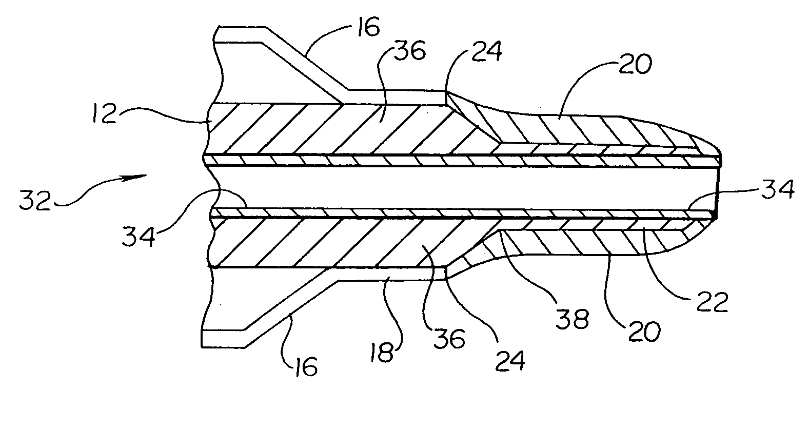
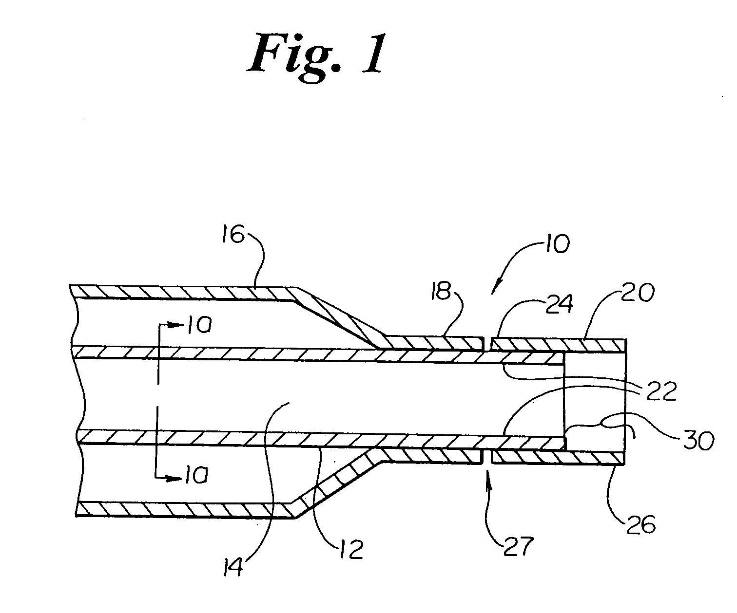
[0038] In the description of the inventive catheters of the present application, the figures used only illustrate the distal end of a typical catheter. It should be understood that the tip designs of the present application may be incorporated and used in the construction of any conventional catheter. It also should be understood that the figures are graphic representations of the inventive catheter designs and should not be construed to represent actual dimensions.

[0039] As indicated above, the present invention is embodied in a variety of form...


PUM


Abstract

The present invention is directed to distal tip designs for catheter, wherein distal tip material is positioned about an inner shaft. The distal tip material may also be used as a tie layer for thermally bonding two incompatible materials together, such as a waist portion of a balloon to the inner shaft.

Description

BACKGROUND OF THE INVENTION [0001] The present invention is related generally to medical devices. More specifically, the present invention is related to catheters. The present invention includes the bonding of incompatible catheter elements to one another and distal tips for catheters, including balloon angioplasty catheters and stent delivery catheters, and methods of making them. [0002] Arterial blockages, which are also called stenoses, are typically caused by the build-up of atherosclerotic plaque on the inside wall of an artery. In fact, several such stenoses may occur contiguously within a single artery. This can result in a partial, or even complete, blockage of the artery. As a result of the danger associated with such a blockage, several methods and procedures have been developed to treat stenoses. One such method is an angioplasty procedure which uses an inflatable balloon to dilate the blocked artery. A typical inflatable angioplasty device, for example, is disclosed in U...

Claims


Application Information

Patent Timeline
Patent Type & Authority Applications(United States)
IPC IPC(8): A61F2/958A61M25/00A61M29/02
CPCA61M25/0069A61M2025/1093A61M25/104A61M25/1034
Inventor HOLMAN, THOMAS J.TOMASCHKO, DANIEL KEITHKLISCH, LEO M.OLSON, RICHARDLYVER, JOSEPH M.DUNN, RICHARDGRISWOLD, DAVIDTANG, NIEWANG, LIXIAO
Owner BOSTON SCI SCIMED INC
Why Eureka
Try Eureka