Data processing system having a plurality of storage systems

a data processing system and storage system technology, applied in data processing applications, fault response, instruments, etc., can solve the problems of data in the third storage system becoming old, data reference and data update time necessary for normal operations extended, and data in the third storage system being abused. to achieve the effect of reducing the data storage area, rapid and effective data transfer or data copying

Inactive Publication Date: 2005-06-16
HITACHI LTD
View PDF67 Cites 39 Cited by
  • Summary
  • Abstract
  • Description
  • Claims
  • Application Information

AI Technical Summary

Benefits of technology

[0010] It is another object of the present invention to conduct data transfer or data copying between a plurality of storage systems, without affecting the communication between the storage systems and the computer.
[0011] It is yet another object of the present invention to reduce a data storage area held in a plurality of storage systems.
[0012] It is still another object of the present invention to conduct rapidly and effectively data transfer or data copying between a plurality of storage systems, so as to produce no effect on the operation of the host computer of the plurality of storage systems.

Problems solved by technology

Another problem is that because data for copying use a communication link between the first computer and the first storage system, those data collide with the data transfer necessary for usual operations and the data reference and data update time necessary for usual operations are extended.
Furthermore, when the data quantity which is the object of copying is large, the time consumed by the data copying processing is increased and data in the third storage system become old.
The resulting problem is that when operations are restarted by using the data of the third storage system, a long time is required to renew the data of the third storage system and the time required to restart the operations is extended.
Therefore, a long time is consumed for data update from the computers, and the time required for data update extends with the increase in the distance between the first storage system and the second storage system.
The resulting problem is that the distance between the two storage systems cannot be made too large.

Method used


Image

  • Data processing system having a plurality of storage systems
  • Data processing system having a plurality of storage systems
  • Data processing system having a plurality of storage systems

Examples


second embodiment

[0190]FIG. 23 illustrates the logical configuration of the data processing system in accordance with the present invention.

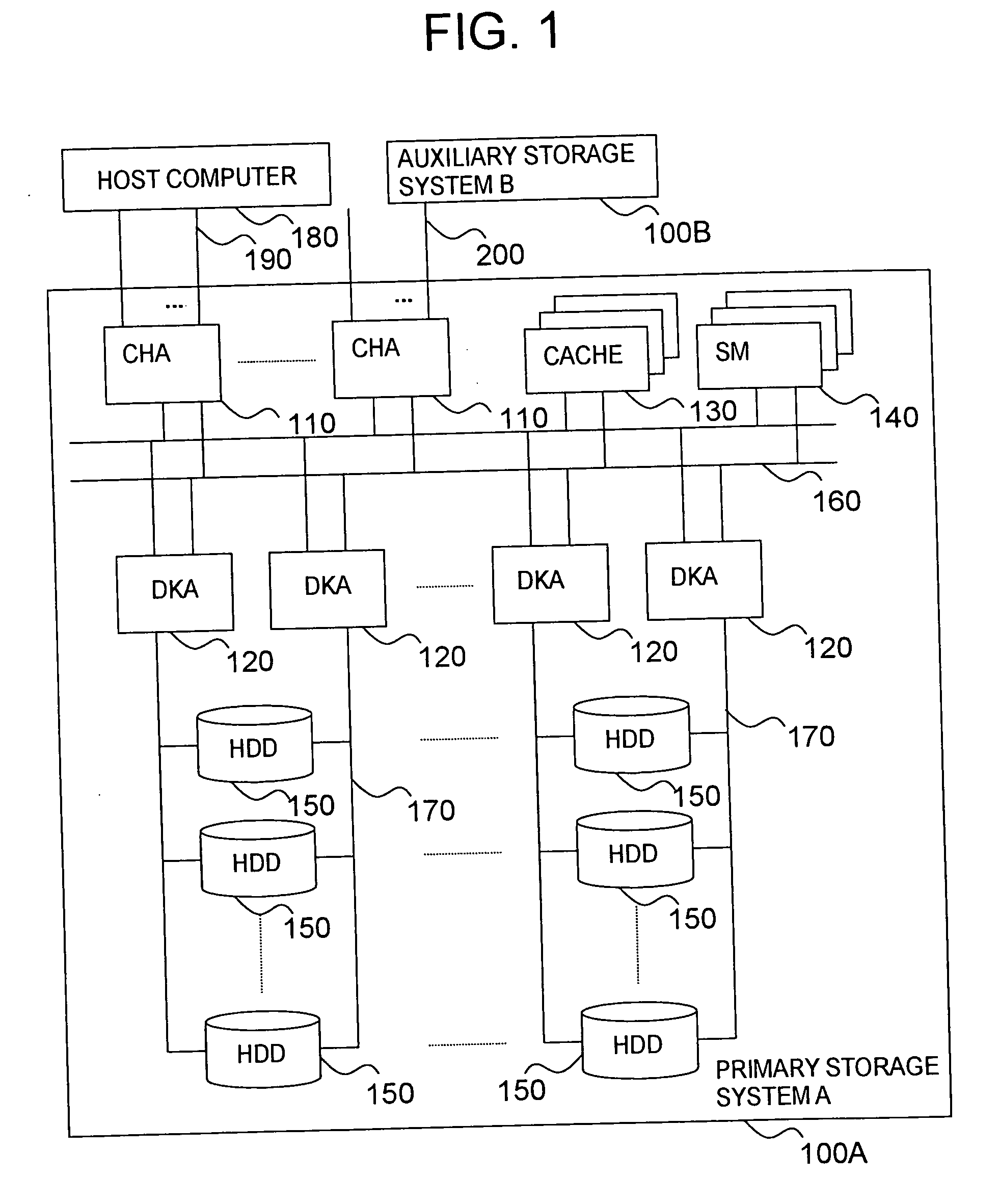
[0191] As shown in FIG. 23, in the present embodiment, a third storage system 100C is added to the primary storage system 100A and the auxiliary storage system 100B. The physical configuration of the storage systems 100A, 100B, and 100C basically may be identical to the configuration that has already been explained with reference to FIG. 1. The host computer 180 and the third storage system 100C are connected by a connection path 190, the third storage system 100C and the primary storage system 100A are connected by the connection path 200, and the primary storage system 100A and the auxiliary storage system 100B are connected by the connection path 200. The third storage system 100C comprises original logical volumes (“ORG 1”, “ORG 2”, and the like) 230 holding respective data on the source of data in the primary logical volumes “DATA 1”, “DATA 2”, and the like...

first embodiment

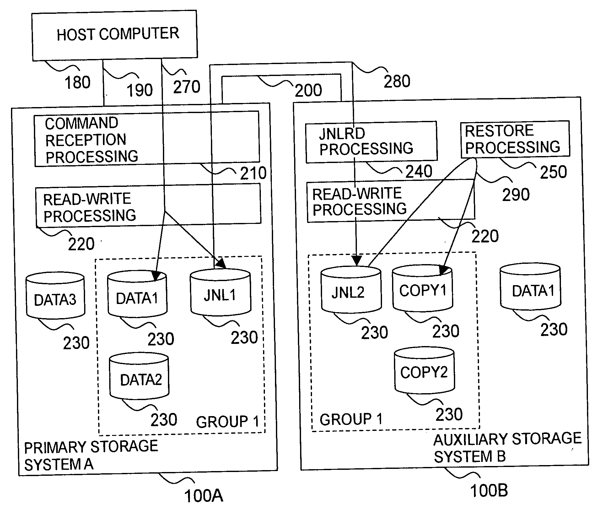
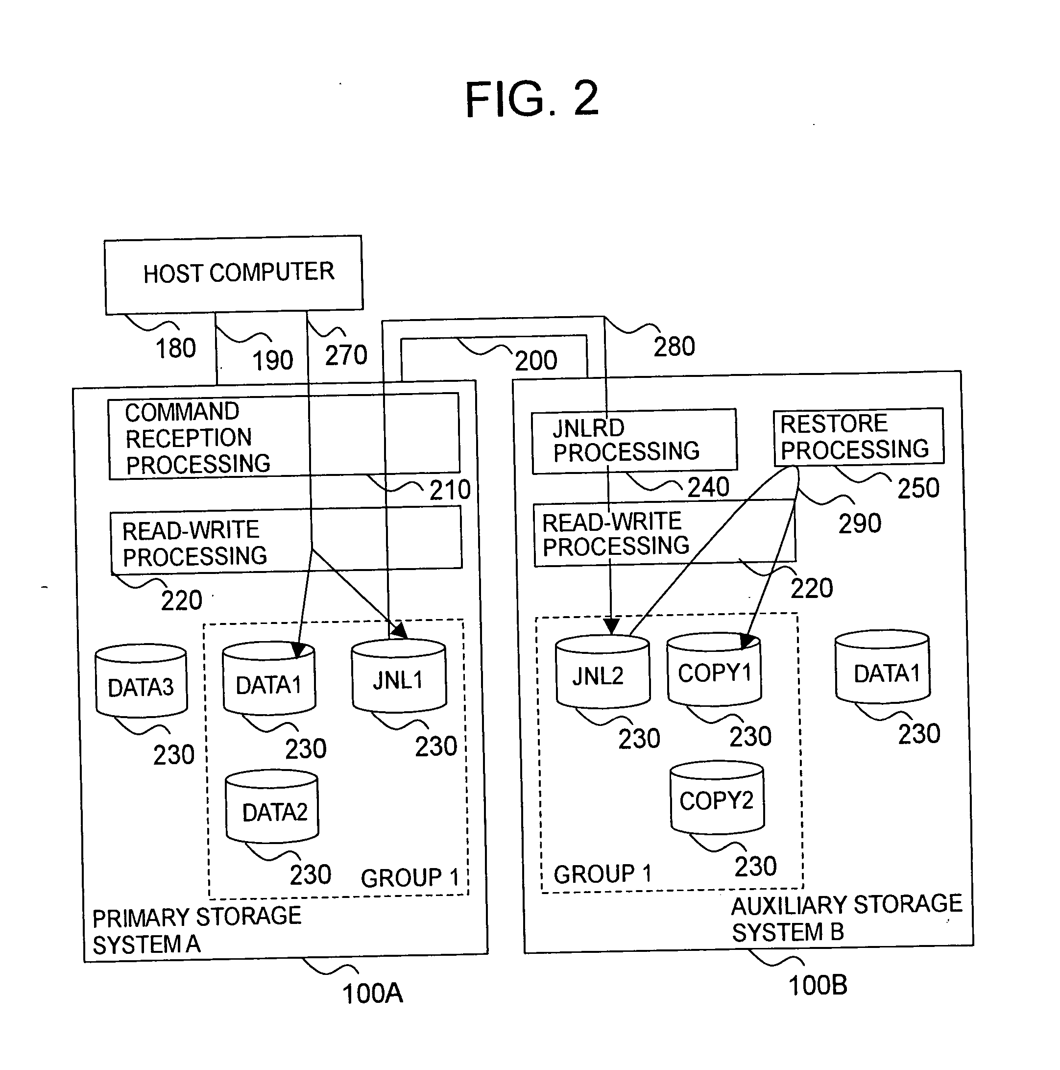
[0193] The primary storage system 100A, as was explained in the first embodiment, receives the aforesaid data write command, updates the data of the required primary logical volume (for example “DATA 1”) 230, and saves the journals of the data update in the journal logical volume (“JNL 1”) 230 by the above-described command reception processing 210 and read-write processing 220 (step 2310).

[0194] The auxiliary storage system 100B reads the journals from the primary storage system 100A by the above-described journal read processing 240 and saves the journals in the journal logical volume (“JNL 2”) 230 by the read-write processing 220. (2320).

[0195] If the journal read command is received from the auxiliary storage system 100B, the primary storage system 100A reads the journals from the journal logical volume (“JNL 1”) 230 by the command reception processing 210 and read-write processing 220 and sends them to the auxiliary storage system 100B (2320).

[0196] The auxiliary storage syst...

third embodiment

[0198]FIG. 24 illustrates the logical configuration of the data processing system in accordance with the present invention.

[0199] As shown in FIG. 24, in the present embodiment, a third storage system 100C is added to the primary storage system 100A and the auxiliary storage system 100B. The physical configuration of the storage systems 100A, 100B, and 100C basically may be identical to the configuration that has already been explained with reference to FIG. 1. The host computer 180 and the third storage system 100C are connected by the connection path 190, the third storage system 100C and the primary storage system 100A are connected by the connection path 200, and the primary storage system 100A and the auxiliary storage system 100B are connected by the connection path 200.

[0200] The primary storage system 100A shows the third storage system 100C as if the primary logical volumes (“DATA 1”, “DATA 2”, and the like) are present, but does not allocate the actual physical storage ar...


PUM


Abstract

It is an object of the present invention to conduct data transfer or data copying between a plurality of storage systems, without affecting the host computer of the storage systems. Two or more auxiliary storage systems 100B, 100C are connected to a primary storage system 100A connected to a host device 180. The auxiliary storage systems 100B, 100C read journals of data update from the primary storage system 100A at respective independent timings, save the journals in prescribed logical volumes JNL 2, JNL 3, produce copying of the data present in the primary storage system 100A based on the journals present in the logical volumes JNL 2, JNL 3 at the independent timings, and save the copies in auxiliary logical volumes COPY 1, COPY 3. The primary storage system 100A holds the journals till both auxiliary storage systems 100B, 100C read the journals and restore. The timing of journal read can be controlled according to the journal quantity, processing load, and the like.

Description

BACKGROUND OF THE INVENTION [0001] 1. Field of the Invention [0002] The present invention relates to a data processing system having a plurality of storage systems, and more particularly to data copying between a plurality of storage systems. [0003] 2. Description of the Related Art [0004] In recent years, a technology relating to data copying between storage systems has gained importance by allowing a data processing system to be able to provide services to a customer even when a failure has occurred in the first storage system, in order to provide continual service to the customer. Technology for copying the information stored in the first storage system into the second and third storage systems was disclosed in the following patent references. [0005] U.S. Pat. No. 5,170,480 discloses a technology in which a first computer connected to a first storage system transfers the data stored in the first storage system to a second computer via a communication link between the first comput...

Claims


Application Information

Patent Timeline
Patent Type & Authority Applications(United States)
IPC IPC(8): G06F3/06G06F11/20G06F12/00
CPCG06F11/2058Y10S707/99952G06F2201/855G06F11/2071
Inventor KASAKO, NAOHISA
Owner HITACHI LTD
Why Eureka
Try Eureka