[0008] Preferred embodiments of the present invention operate to prevent toilet overflow in a cost-effective and reliable manner. In addition, preferred embodiments may be integrated into a toilet assembly during manufacture or retrofitted into an existing toilet, preferably with little or no modification of the standard toilet. Embodiments intended for
retrofitting in existing toilets preferably require a low level of skill to install.
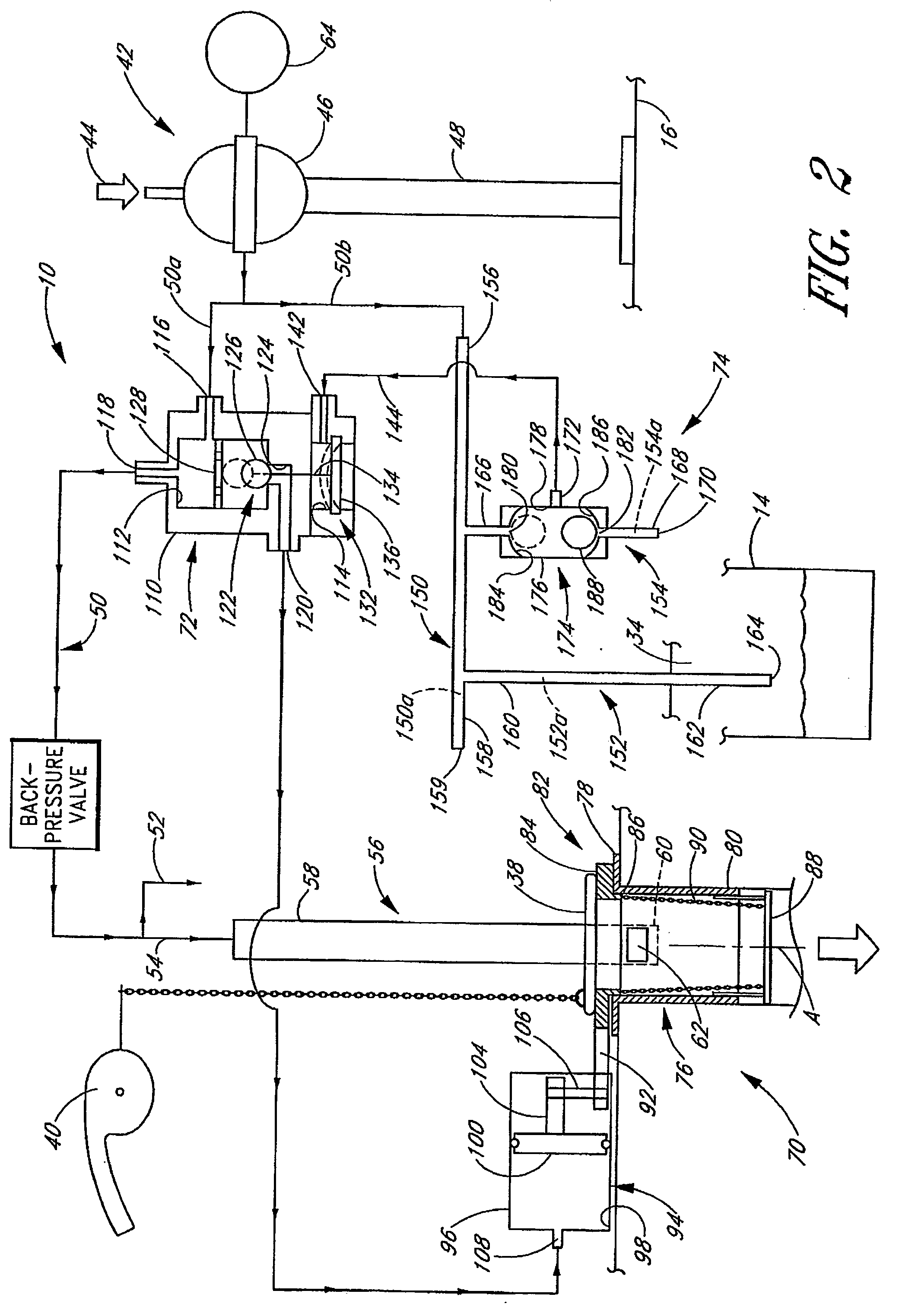
[0009] A preferred embodiment of the present invention involves a toilet overflow prevention device comprising an overflow valve assembly having a secondary valve, a fluid cylinder and a transmission mechanism. The secondary valve is positioned between a primary flush valve of the toilet and a bowl of the toilet. The secondary valve is configured to be rotatable from an open position, wherein water is permitted to flow through the secondary valve, to a closed position, wherein water is substantially prevented from flowing from a tank of the toilet to the bowl. The fluid cylinder includes a cylinder member defining a bore and a
piston. The
piston is configured for translation within the bore and defines a variable volume fluid chamber with the cylinder member. The transmission mechanism is configured to convert translation of the
piston into rotation of the secondary valve. The piston is movable from a relaxed position to a displaced position in response to water being introduced into the fluid chamber to move the secondary valve from the open position to the closed position. The device also includes a control valve configured to receive a flow of supply water from a toilet
water supply source. The control valve selectively directs a portion of the supply water to the fluid chamber. The control valve is movable between a
normal position and an overflow position. In the
normal position, substantially no water is directed to the fluid chamber and in the overflow position, supply water is directed to the fluid chamber. The device further includes a water
level sensor configured to sense an above-normal water level in the bowl of the toilet. In response to an above-normal water level, the control valve is moved from the
normal position to the overflow position, thereby moving the secondary valve from the open position to the closed position and preventing water from flowing from the tank into the bowl.
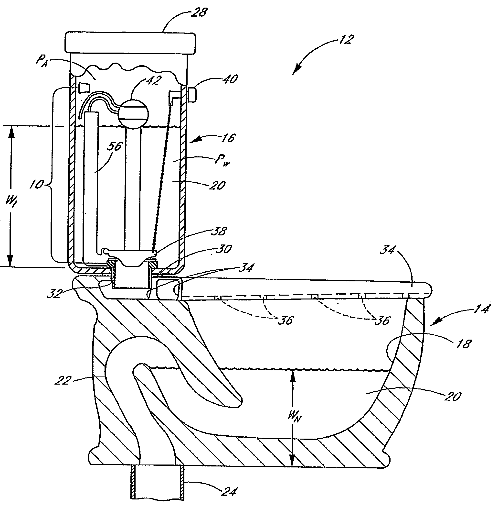
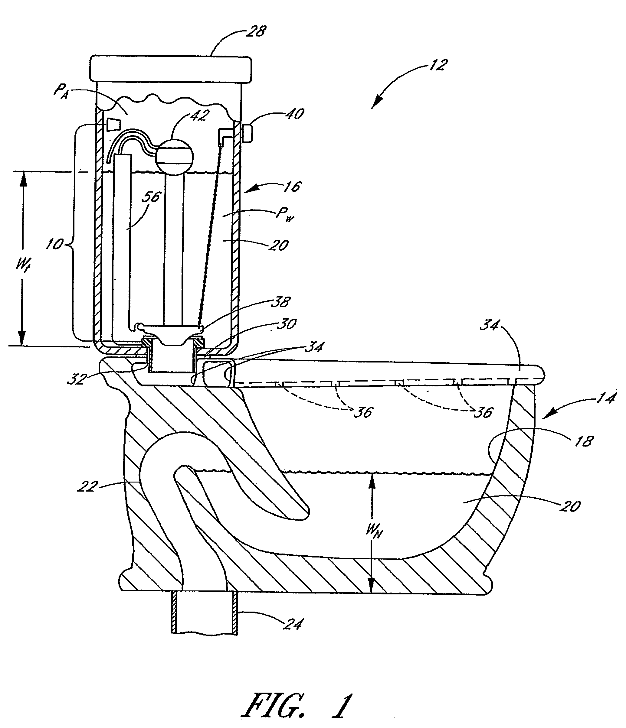
[0010] Another embodiment of the present invention involves a toilet overflow prevention device for use with a toilet having a tank, a bowl, a passage connecting the tank and the bowl, and a flush valve selectively permitting water to move from the tank to the bowl. The device comprises an
actuator including an overflow valve having an open position, wherein water is permitted to flow past the valve, and a closed position, wherein water is substantially prevented from flowing past the valve and into the bowl. A water
level sensor is configured to sense an above-normal water level in the bowl of the toilet. The water level sensor includes a main flow passage having a first end and a second end. The first end of the main flow passage is configured to receive a flow of water from a
water supply source of the toilet and the second end defines a
discharge opening. The water level sensor also includes a first
branch flow passage having a first end and a second end. The first end communicates with the main flow passage and the second end defines a first inlet opening positioned at the above-normal water level. The water level sensor also includes a second
branch flow passage having a first end, a second end and a valve between the first and second ends. The first end communicates with the main flow passage and the second end defines a second inlet opening. When the water level is below the first inlet opening, the valve is moved to a first position and the
actuator permits the overflow valve assembly to move to the open position. When the water level is above the first inlet opening, the valve is moved to a second position and the
actuator moves the overflow valve from the open position to the closed position, thereby preventing water from flowing from the tank into the bowl.
[0013] Still another preferred embodiment is a toilet overflow prevention
system including an overflow valve configured to substantially prevent
water flow from a tank of the toilet to a bowl of the toilet through the overflow valve when the overflow valve is in a closed position. The overflow valve is configured to move to the closed position in response to a supply of water directed to a fluid chamber of the overflow valve. A control valve is configured to selectively direct a supply of water to the overflow valve. The control valve includes a fluid inlet, and first fluid outlet and a valve body. The inlet receives a supply of water from a
water supply source of the toilet. The first outlet is configured to direct a portion of the supply of water to the overflow valve. The valve body is moveable between a first position in which fluid communication between the inlet and the first outlet is substantially prevented and a second position in which fluid communication between the inlet and the first outlet is permitted. A variable
volume control chamber is configured to act on the valve body, wherein at a first volume of the control chamber, the valve body is in the first position and at a second volume of the control chamber, the valve body is moved to the second position. A water level sensor is configured to sense an above-normal water level in the bowl and communicate with the control chamber. The water level sensor is configured to change a pressure within the control chamber to move the control chamber from the first volume to the second volume.

