Vacuum cleaner

Inactive Publication Date: 2005-06-23
HOOVER LIMITED
View PDF6 Cites 26 Cited by
  • Summary
  • Abstract
  • Description
  • Claims
  • Application Information

AI Technical Summary

Benefits of technology

[0015] The present invention thus provides a clean and hygienic way of empting the receptacle by allowing the fine and coarse dirt to be emptied in two distinct operating stages, thereby avoiding the problem of dust contamination when all of the dirt is released in an uncontrolled sin

Problems solved by technology

However, a disadvantage of re-usable dirt receptacles is that the receptacles are often dirty to handle and clouds of dirt and dust can be emitted into the atmosphere when the receptacles are emptied, with the obvious health risks and resultant contamination of the vacuum cleaner and the user's environment with a layer of dust.
One of the main disadvantages of known cyclonic vacuum cleaners is that the procedure for emptying their dirt receptacles is a potentially dirty and unhygienic process.
This problem is exacerbated because fine dirt typically collects at the base of the dirt receptacle, with coarse and fibrous dirt lodging in the upper region of the receptacle.
When the dirt receptacle is inverted for emptying, the entire mass of dirt falls in an uncontrolled manner into the vessel used for its final disposal, typically a dustbin or refuse bag.
This uncontrolled discharge usually results in the lighter dirt fractions being disturb

Method used


Image

  • Vacuum cleaner
  • Vacuum cleaner
  • Vacuum cleaner

Examples


Example

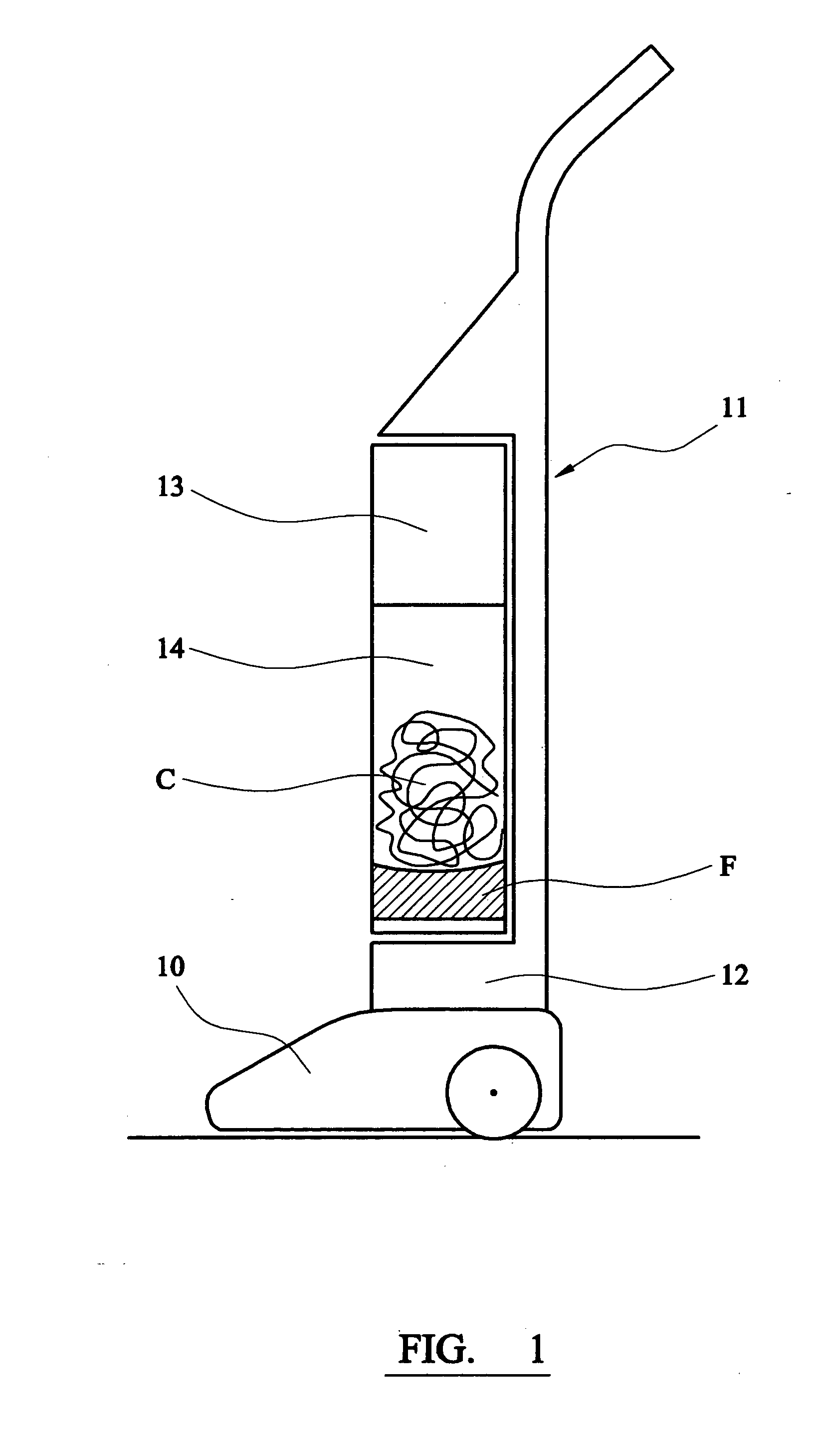
[0046] Referring to FIG. 1 of the drawings, there is shown an upright vacuum cleaner comprising a wheeled suction head 10, to which a body portion 11 is pivoted for movement between an upright position and an inclined operative position. A motor and fan are mounted in a bottom portion 12 of the body 11 of the cleaner.

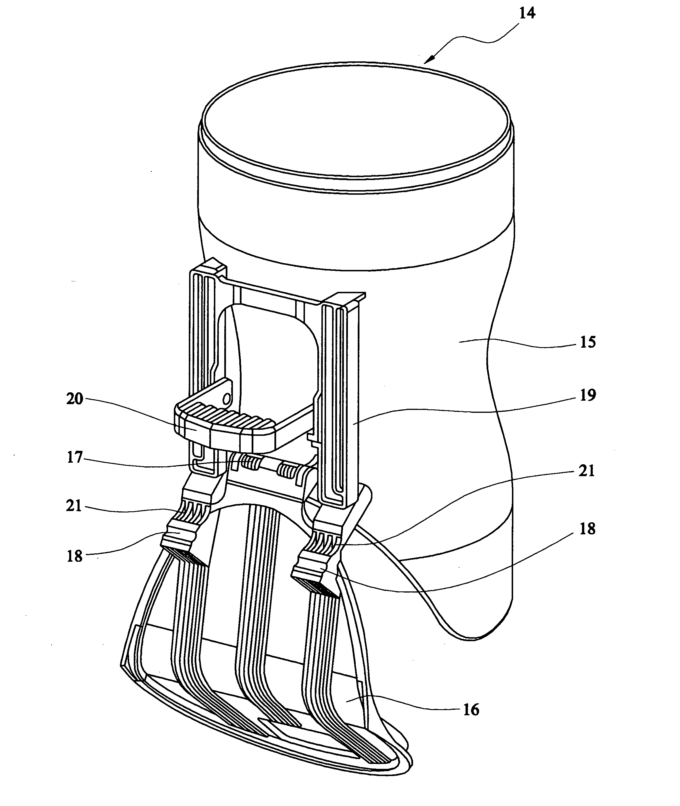
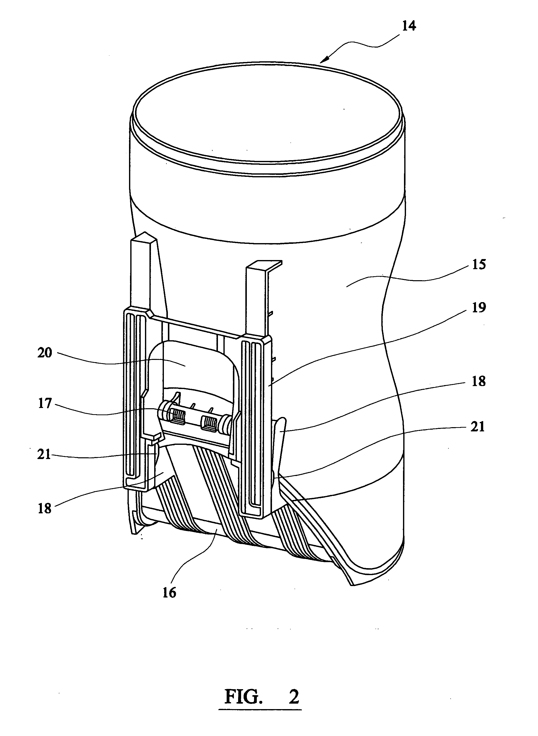
[0047] A separation unit 13 mounted in the body 11 of the cleaner comprises a cyclone separator and a filter. In use, the fan induces an airflow through the cleaner from the suction head 10 through the separation unit 13, where dirt and dust separated from the airflow by the cyclone is collected in a removable dirt collection bin 14 mounted directly below the separation unit 13. The cyclone separator comprises a cylindrical wall and for practical purposes, the side wall of the collection bin 14 is a downward extension of the wall of the cyclone.

[0048] The cyclonic separation action causes the finer dirt particles F to collect at the bottom of the collection bin 14 bel...


PUM


Abstract

A vacuum cleaner comprises a rigid dirt receptacle 14 having an outlet at one end, through which the collected dirt and dust can be emptied, a flap 16 for closing the outlet, and an actuator 58 for moving the flap 16 between a closed position and an open position, the actuator 58 being operable to control the position of the flap 16 between the open and closed positions.
A location is provided at a partially opened position of the flap 16, at which position fine dirt and dust can be emptied through the restricted outlet in a controlled manner. The restricted size of the outlet retains any coarse and fibrous dirt inside the receptacle 14. Once the fine dirt has been emptied, the flap 16 can be moved to its fully open position to allow the coarse dirt and fibrous matter to be emptied from the receptacle 14 separately from the fine dust.

Description

BACKGROUND OF THE INVENTION [0001] 1. Field of the Invention [0002] This invention relates to a vacuum cleaner. [0003] 2. Related Background Art [0004] Vacuum cleaners conventionally comprise a permeable dust bag, which filters and retains the dirt and dust drawn into the vacuum cleaner by the induced air flow. Nowadays, it has become popular to provide vacuum cleaners, in which the separated dirt and dust is collected in a rigid dirt receptacle that can be emptied and re-used. Such so-called bagless cleaners alleviate the need to purchase and replace the dust bags. However, a disadvantage of re-usable dirt receptacles is that the receptacles are often dirty to handle and clouds of dirt and dust can be emitted into the atmosphere when the receptacles are emptied, with the obvious health risks and resultant contamination of the vacuum cleaner and the user's environment with a layer of dust. [0005] Many bagless vacuum cleaners nowadays comprise a cyclonic separator, which deposits the...

Claims


Application Information

Patent Timeline
IPC IPC(8): A47L5/28A47L9/10A47L9/16
CPCA47L9/1683A47L5/28
Inventor MACLEOD, EUAN SKINNERRICHARDSON, ROSSHENDERSON, CHRISTOPHER RICHARD
Owner HOOVER LIMITED
Why Eureka
Try Eureka