Electronic component mounting apparatus

a technology for mounting apparatuses and components, applied in the direction of metal-working machine components, manufacturing tools, instruments, etc., can solve problems such as errors in the positional relationship between axes, and achieve the effect of increasing driving power and reducing driving power

Active Publication Date: 2005-06-23
YAMAHA MOTOR CO LTD
View PDF8 Cites 9 Cited by
  • Summary
  • Abstract
  • Description
  • Claims
  • Application Information

AI Technical Summary

Benefits of technology

[0007] The invention provides an electronic component mounting apparatus that includes a component feeding unit feeding an electronic component, a beam moving in a first direction along a first drive axis and a second drive axis, a first driven portion moving the beam along the first drive axis, a second driven portion moving the beam along the second drive axis, a mounting head that moves along the beam for picking the electronic component up from the component feeding unit and mounting the electronic component on a printed board, a memory storing data on a picking up position of the electronic component and data on a mounting position of the electronic component on the printed board, a controller sending a command, which is generated based on the data stored in the memory, to move the beam to a position for the picking up and the mounting of the electronic component, a first driver circuit providing a first control electric current to the first driven portion in response to the command from the controller, and a second driver circuit providing a second control electric current to the second driven portion in response to the command from the controller. The first driver circuit is configured to calculate the difference between positions of the first and second driven portions along the first direction and to adjust the first control electric current based on the difference so as to increase a driving power of the first driven portion when the first driven portion is behind the second driven portion along the first direction and to reduce the driving power when the first driven portion is ahead of the second driven portion along the first direction.

Problems solved by technology

However, although it is desirable that a positional relationship between two axes is the same at any time when the beam is operated by two drive sources, a load imbalance between the axes, a synchronizing error in command sending to each of the axes, a friction imbalance between the axes, a difference between linear scales of the axes, and so on can cause errors in the positional relationship between the axes.

Method used


Image

  • Electronic component mounting apparatus
  • Electronic component mounting apparatus
  • Electronic component mounting apparatus

Examples


Embodiment Construction

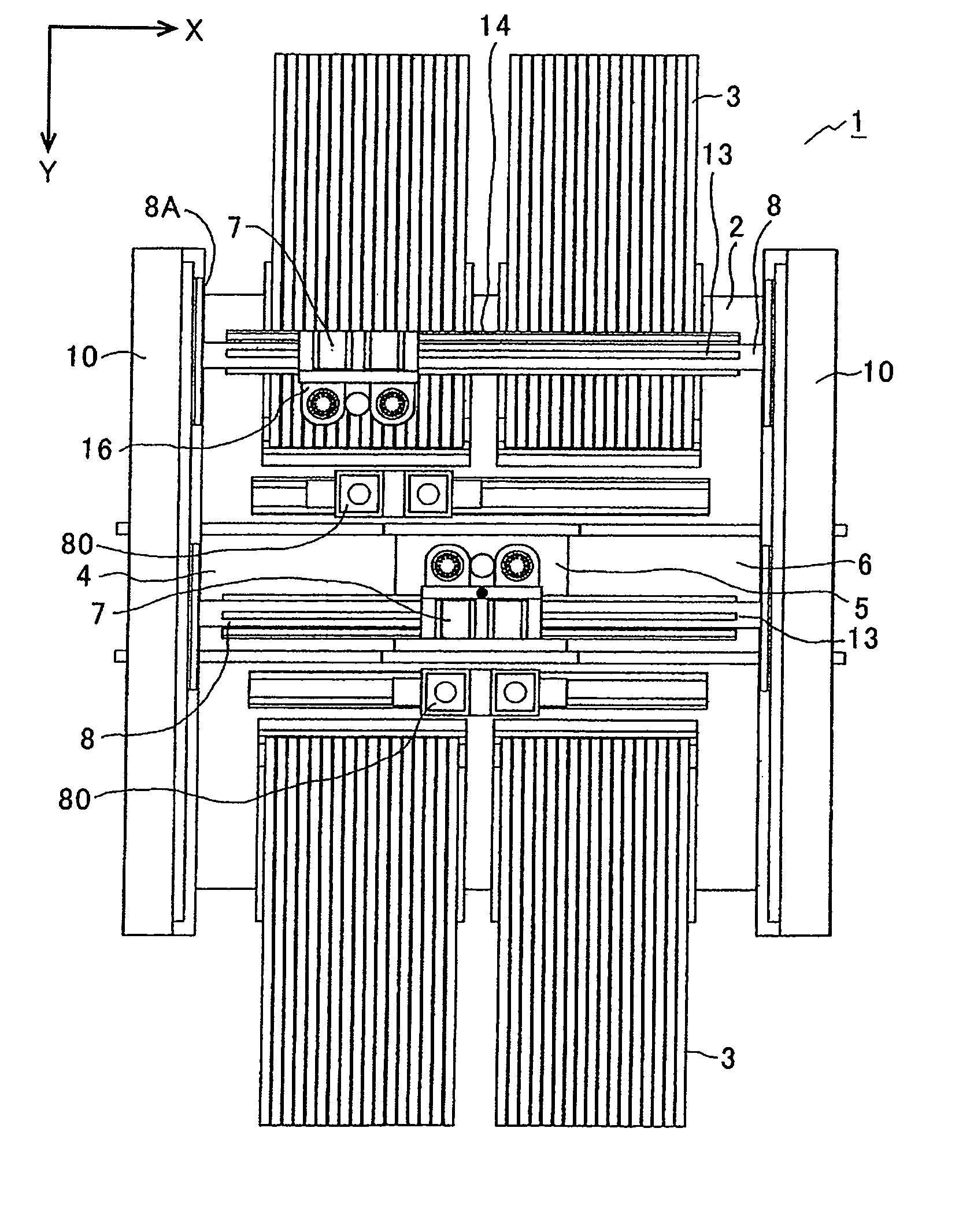
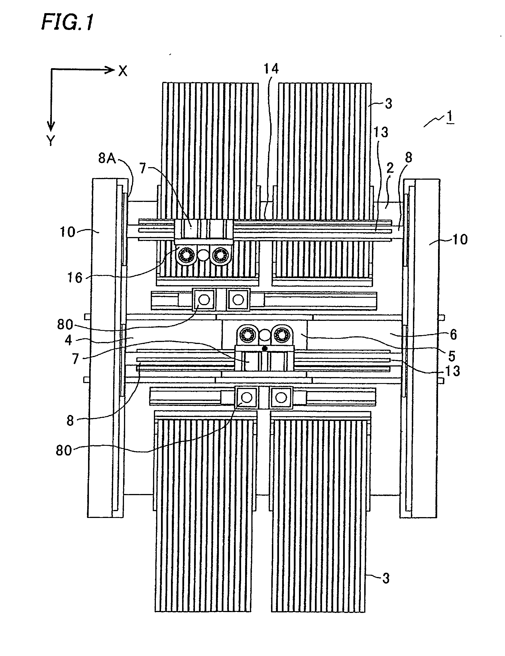
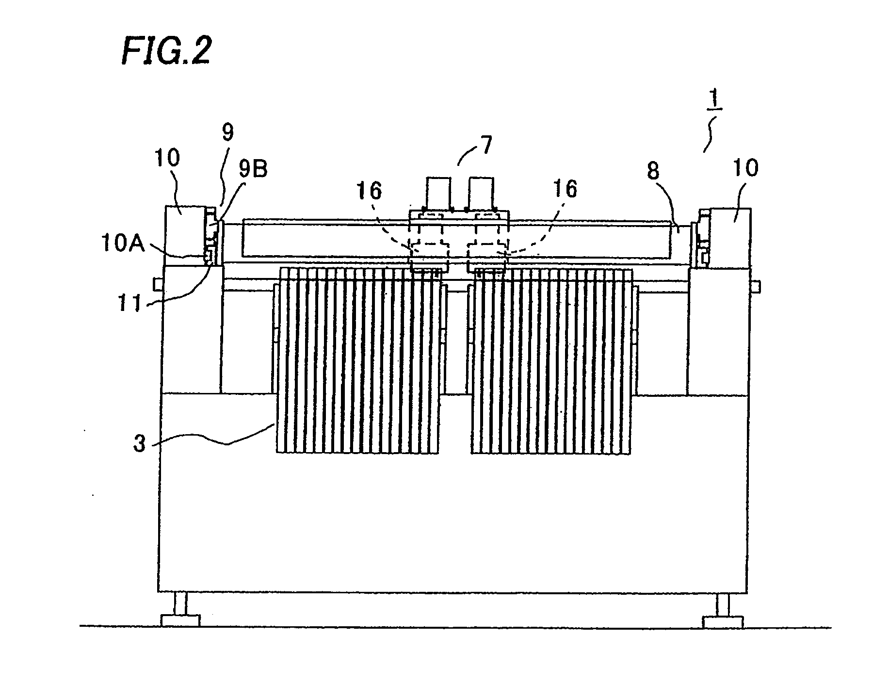
[0028] An embodiment of an electronic component mounting apparatus of the invention will be described with reference to the attached drawings. FIG. 1 is a plan view of an electronic component mounting apparatus 1, FIG. 2 is a front view of the electronic component mounting apparatus 1, and FIG. 3 is a right side view of the electronic component mounting apparatus 1. A plurality of component feeding units 3 as a component feeding device for feeding a variety of electronic components one by one to each of component feeding positions (component pick-up positions) is attachably and detachably aligned and fixed on a base 2 in the apparatus 1. A feed conveyer 4, a positioning portion 5, and a discharge conveyer 6 are provided between groups of the units 3 facing each other. The feed conveyer 4 conveys a printed board P received from an upstream to the positioning portion 5, an electronic component is mounted on the printed board P positioned by a positioning device (not shown) in the posi...


PUM

PropertyMeasurementUnit
electric currentaaaaaaaaaa
driving poweraaaaaaaaaa
poweraaaaaaaaaa

Abstract

The invention is directed to quick adjustment of a positional relationship between two axes when an error occurs in the positional relationship between the axes when a beam is moved by two drive sources. According to movement of the beam for component picking and mounting operations, linear scale signals (outputs relating to positions of one drive axis and another drive axes) from linear scale reading heads are inputted to a Y2 driver and a Y1 driver respectively. Since each of the Y2 driver and the Y1 driver has a calculation means and a control means, when inputted with both the linear scale signals, each of the Y2 driver and the Y1 driver calculates a difference between positions of the drive axes of the beam by the calculation means, and controls a moving member of a linear motor by the control means based on the difference so as to increase thrust of one drive axis in a case where the one drive axis is in a more backward position than another drive axis and reduces the thrust of one drive axis in a case where the one drive axis in a more forward position than another drive axis.

Description

CROSS-REFERENCE OF THE INVENTION [0001] This invention is based on Japanese Patent Application No. 2003-371869, the content of which is incorporated by reference in its entirety. BACKGROUND OF THE INVENTION [0002] 1. Field of the Invention [0003] This invention relates to an electronic component mounting apparatus having a plurality of component feeding devices aligned on a base and feeding an electronic component to a component pickup position, a beam movable in one direction by two drive sources, and a mounting head with suction nozzles movable in an orthogonal direction to the moving direction of the beam and movable between the component feeding devices and a printed board to pick the electronic component up from the component feeding device and mount the component on the printed board. [0004] 2. Description of the Related Art [0005] This type of electronic component mounting apparatus is disclosed, for example, in Japanese Patent Application Publication No. 2002-299898. Specifi...

Claims


Application Information

Patent Timeline
Patent Type & Authority Applications(United States)
IPC IPC(8): H05K13/04
CPCH05K13/0452Y10T29/53087Y10T29/53191Y10T29/53187Y10T29/53178Y10T29/53091Y10T29/53174H05K13/0406H05K13/04
Inventor AOKI, AKIRAFUKUSHIMA, HIDEAKIOYAMA, KAZUYOSHINUSHIYAMA, SHUJIIMOTO, TAKUYA
Owner YAMAHA MOTOR CO LTD
Why Eureka
Try Eureka