Unlock mechanism for a rotary door operator

Active Publication Date: 2005-06-23
WABTEC HLDG CORP
View PDF7 Cites 26 Cited by
  • Summary
  • Abstract
  • Description
  • Claims
  • Application Information

AI Technical Summary

Benefits of technology

[0019] It is, therefore, one of the primary objects of the present invention

Problems solved by technology

One of the main disadvantages of these designs is that loss of fluid pressure will cause downward movement of the door, thus disengaging such mating wedges in lift-and-lock applications or simply unlock the door in zero-lead applications and, more particularly, the loss of fluid pressure will create a hazardous condition due to an unlocked door.
There are several disadvantages related to this type of lock mechanism.
As it is well known in the art, presense of frictional forces causes premature wear and reduces reliability of the design.
In the third aspect, manual un

Method used


Image

  • Unlock mechanism for a rotary door operator
  • Unlock mechanism for a rotary door operator
  • Unlock mechanism for a rotary door operator

Examples


Embodiment Construction

, particularly, when the detailed description is taken in conjunction with the attached drawing figures and with the appended claims.

BRIEF DESCRIPTION OF THE DRAWINGS

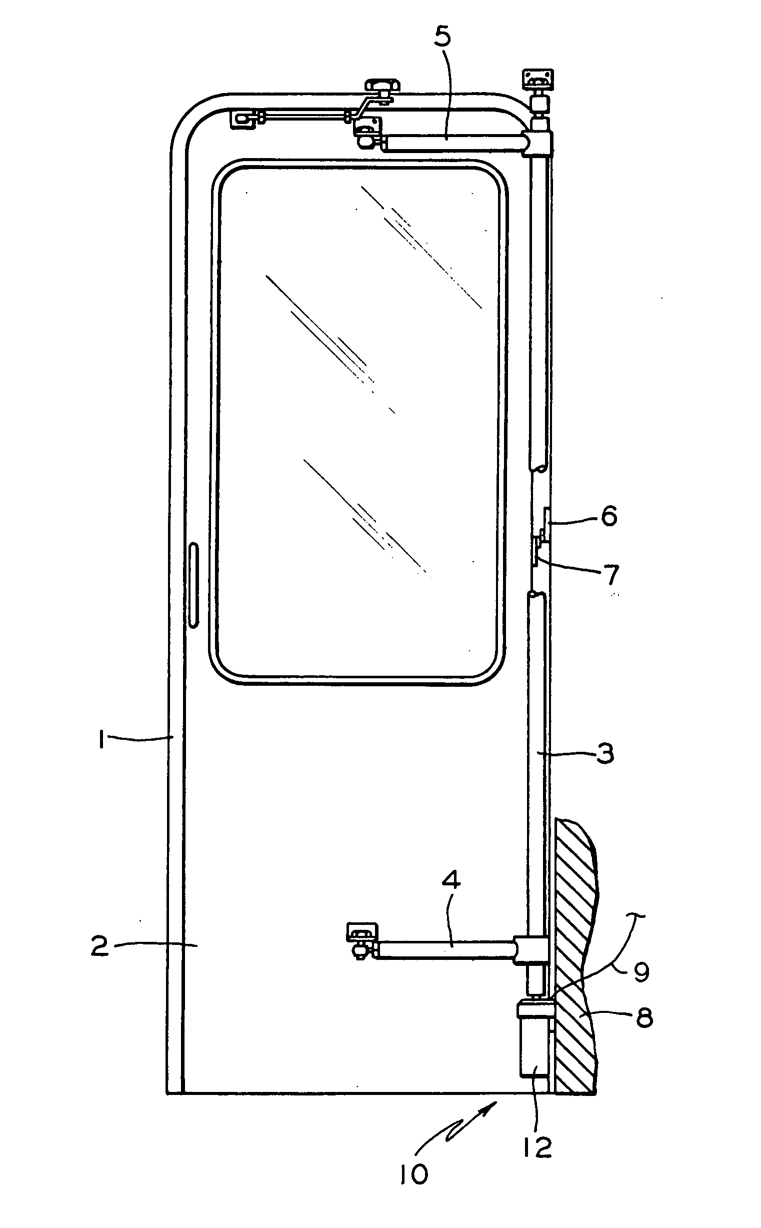
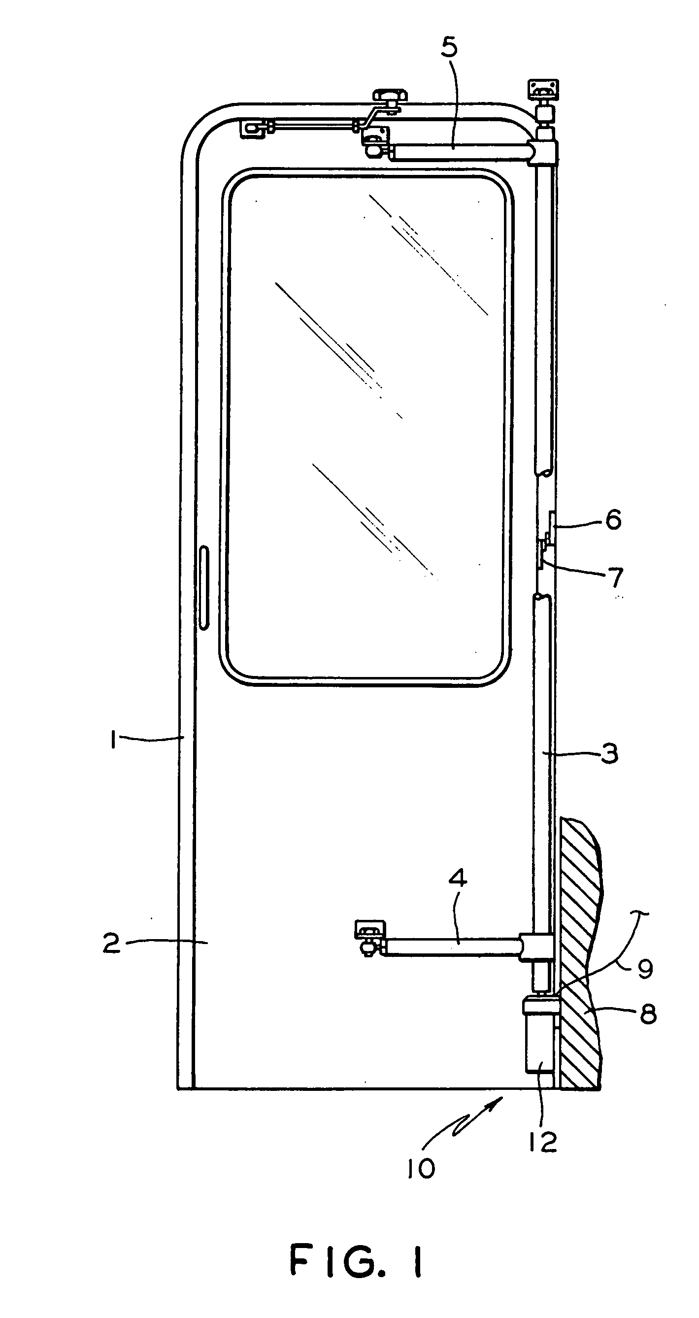
[0024]FIG. 1 is a plan view of a typical door system utilizing a rotaty door operator;

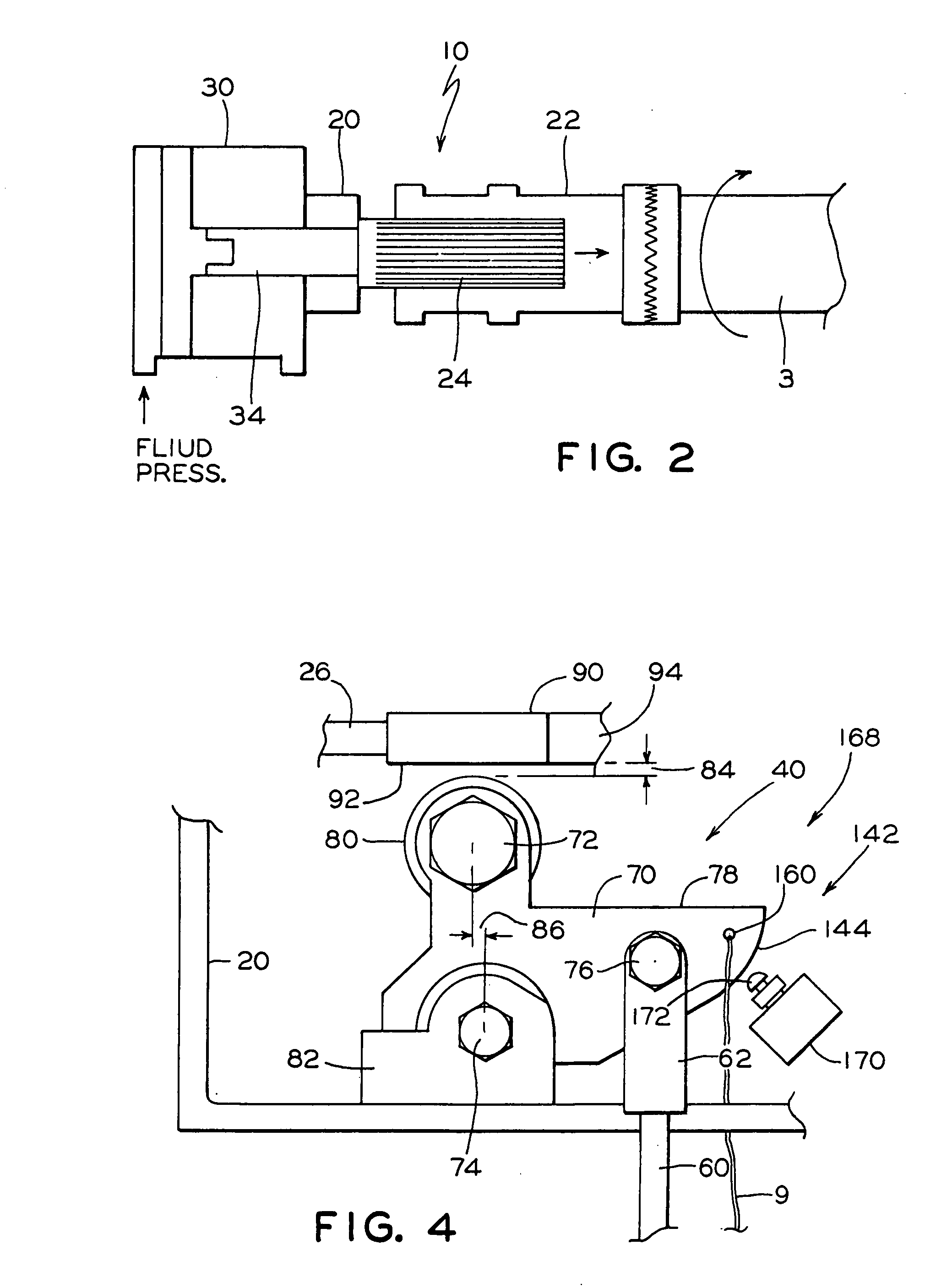
[0025]FIG. 2 is a diagramatic view of the rotary door operator;

[0026]FIG. 3 is a side elevation view particluraly showing a first embodiment of the unlock mechanism of the present invention;

[0027]FIG. 4 is a side elevation view particluraly showing another embodiment of the unlock mechanism of the present invention;

[0028]FIG. 5 is a perspective view of the unlock mechanism, according to the presently preferred embodiment of the present invention;

[0029]FIG. 6 is a schematic diagram of the control system arrangement; and

[0030]FIGS. 7a-7d are plan views of the alternative embodiments of the present invention.

BRIEF DESCRIPTION OF THE PREFERRED AND ALTERNATIVE EMBODIMENTS OF THE PRESENT INVENTION

[0031] Before describing the inventi...


PUM


Abstract

An unlock mechanism for a rotary door operator of a transit vehicle includes a pivotally disposed unlock member adapted for rotating a lock member into an unlock position and activating a valve for discharging the fluid pressure from the drive cylinder to enable manual opening of the door. A spring is provided for biasing the unlock member to a non-activated position. The unlock member may be activated either with a cable or a lever handle. A lock sensing switch provides a feedback on the lock condition to the transit vehicle control system. Additionally, a guiding bracket is provided for securing the cable in proximity of the unlock member.

Description

CROSS-REFERENCE TO CO-PENDING APPLICATIONS [0001] This application is closely related to co-pending U.S. Ser. No. ______ entitled “Lock Mechanism for a Rotary Door Operator”, to co-pending U.S. Ser. No. ______ entitled “Rotary Door Operator”, filed concurrently herewith. These applications being assigned to the assignees of the present invention and disclosures of these co-pending applications are hereby incorporated by reference thereto.FIELD OF THE INVENTION [0002] The present invention relates, in general, to transit vehicle door systems and, more particularly, the instant invention relates to a rotary door operator and, yet more particularly, the instant invention relates to a rotary door operator having a “zero-lead” or a “Lift and Lock” locking feature. BACKGROUND OF THE INVENTION [0003] Prior to the development of the present invention, as is generally well known in the art, a rotary door operator is mainly used in the inter-city bus coaches. These rotary operators are availa...

Claims


Application Information

Patent Timeline
IPC IPC(8): B60J5/06B61D19/02E05F15/00E05F15/04
CPCB60J5/062B61D19/026E05Y2201/22E05Y2201/244E05Y2201/246E05Y2201/448E05F15/53E05Y2800/262E05Y2900/506E05Y2900/51E05Y2201/654E05F15/40E05F15/49E05Y2800/25
Inventor TONG, HAIBOKRBEC, MARIANNE
Owner WABTEC HLDG CORP
Why Eureka
Try Eureka