Cylinder head gasket with integral filter element

a technology of filter element and cylinder head, which is applied in the direction of engine seals, lubricant mounting/connection, lubrication elements, etc., can solve the problems of cylinder head components such as lifters, cam phasers, cylinder deactivation solenoids, becoming lodged with debris, and being much more sensitive to manufacturing and wear debris, etc., to achieve the effect of improving the arrangement of cylinder head gaskets

Active Publication Date: 2005-06-23
FCA US
View PDF2 Cites 18 Cited by
  • Summary
  • Abstract
  • Description
  • Claims
  • Application Information

AI Technical Summary

Benefits of technology

[0006] Accordingly, an improved cylinder head gasket arrangement for an engine is provided. The cylinder head gasket includes an opening positioned in the gasket that is in alignment with an engine oiling circuit passage to allow oil to flow from a cylinder block through the gasket to a cylinder head. The gasket further includes a filter element attached to the gasket relative to the gasket opening and arranged to provide a barrier to debris in the oiling circuit.

Problems solved by technology

The use of these tighter clearances typically results in an engine being much more sensitive to manufacturing and wear debris.
Even with an oil filter, it is not uncommon for cylinder head components such as lifters, cam phasers and cylinder deactivation solenoids to become lodged with debris.

Method used


Image

  • Cylinder head gasket with integral filter element
  • Cylinder head gasket with integral filter element
  • Cylinder head gasket with integral filter element

Examples


Embodiment Construction

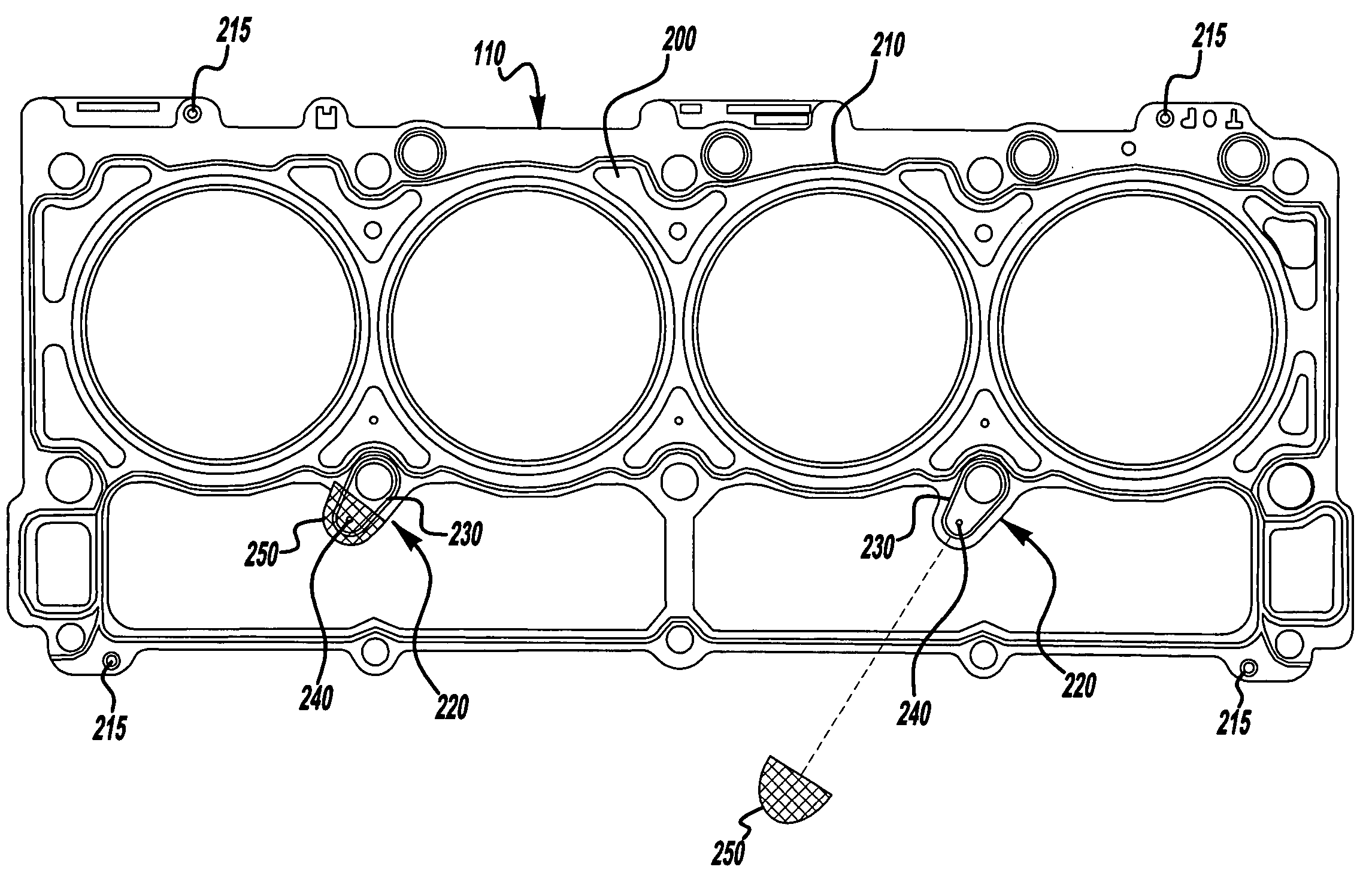
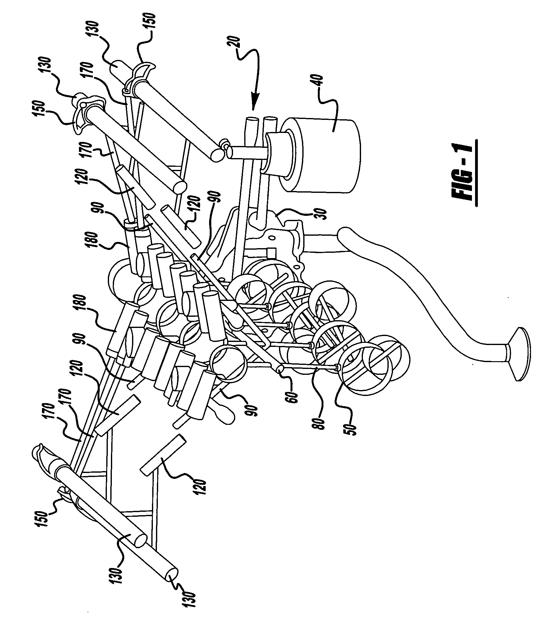
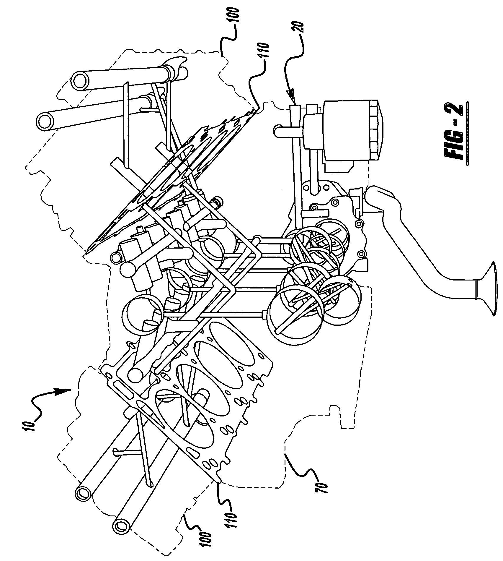
[0013] In the following description, several well-known features of an internal combustion engine are not shown or described so as not to obscure the present invention. Referring now to the drawings, FIGS. 1 and 2 illustrate an exemplary embodiment of an internal combustion engine 10 with an oiling circuit 20 that interfaces with a cylinder head gasket 110 including an integral filter element in accordance with the present invention. More specifically, FIG. 1 illustrates the engine oiling circuit 20 without corresponding engine structure and FIG. 2 illustrates engine oiling circuit 20 positioned in an internal combustion engine 10 and interfacing with cylinder head gasket 110.

[0014] As best seen in FIGS. 1 and 2, engine oiling circuit 20 provides a path for oil flow from an oil pump 30 through an oil filter 40 and into an oil feed passage referenced generally as 80. Oil then flows generally into a main oil gallery 60 located in cylinder block 70 through a plurality of the feed pass...


PUM


Abstract

A cylinder head gasket for an engine is provided. The gasket includes an opening positioned in a gasket substrate and arranged to align with an engine oiling circuit passage to allow oil to flow from a cylinder block through the gasket to a cylinder head. The gasket further includes a filter element attached to the gasket relative to the opening and arranged to provide a barrier to debris in the oiling circuit.

Description

FIELD OF THE INVENTION [0001] The present invention relates generally to a gasket for an engine and, more particularly, to a cylinder head gasket with a filtering element for an internal combustion engine. BACKGROUND OF THE INVENTION [0002] With the onset of more stringent fuel economy and emission standards, internal combustion engines used in today's vehicles are being designed with much tighter operating clearances. These tighter clearances are typically associated with main bearings, connected rod bearings, and valve train components such as hydraulic lifters, lash adjusters, cam phasers, hydraulic tensioners, hydraulic cylinder deactivation solenoids and similarly oiled components. Many of the aforementioned components, such as the hydraulic valve train componentry, run with 5-10 micron clearances during normal engine operation. [0003] The use of these tighter clearances typically results in an engine being much more sensitive to manufacturing and wear debris. Even with an oil ...

Claims


Application Information

Patent Timeline
Patent Type & Authority Applications(United States)
IPC IPC(8): F01M1/12F02F11/00F16J15/06F16J15/08
CPCF02F11/002F16J15/0818F16J15/064
Inventor GORGAS, STEVEN J.LEFEBVRE, MICHAEL C.
Owner FCA US
Why Eureka
Try Eureka