Power supply methods and apparatus

a technology of power supply and cooking platform, applied in the direction of frequency-division multiplex, instruments, stoves or ranges, etc., can solve the problem of pre-set power supply limit available for cooking platform us

Active Publication Date: 2005-06-23
HAIER US APPLIANCE SOLUTIONS INC
View PDF15 Cites 40 Cited by
  • Summary
  • Abstract
  • Description
  • Claims
  • Application Information

AI Technical Summary

Problems solved by technology

Once the cooking platform is connected within a household, there wil...

Method used


Image

  • Power supply methods and apparatus
  • Power supply methods and apparatus
  • Power supply methods and apparatus

Examples


Embodiment Construction

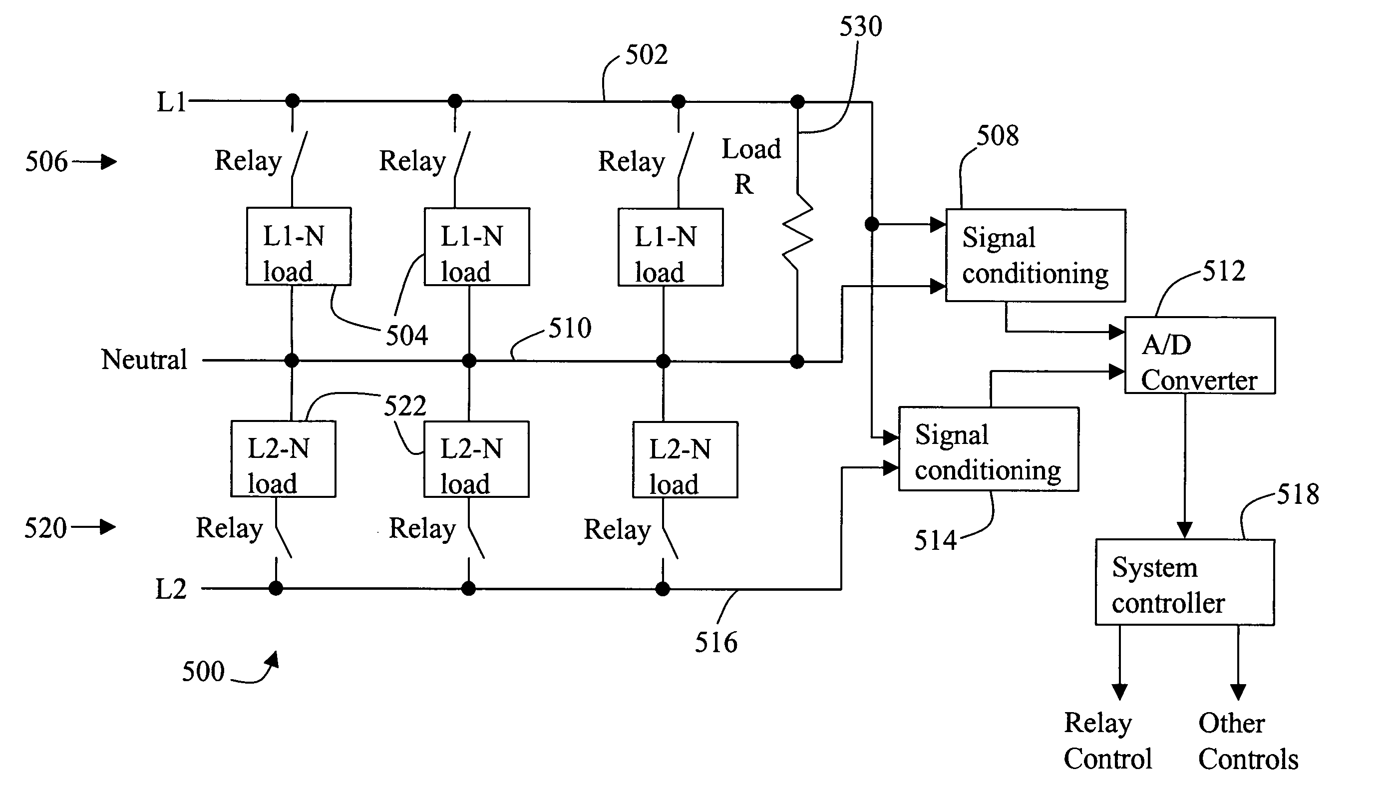
[0015] The present invention is directed, in one aspect, to operation of an oven that includes at least two electrical devices on different 120 volt (V) circuits which together form a 240 V circuit. Although one specific embodiment of a radiant / microwave cooking oven is described below, it should be understood that the present invention can be utilized in combination with many other such ovens and is not limited to practice with the oven described herein. For example, the oven described below is an over the range type oven. The present invention, however, is not limited to practice with just over the range type ovens and can be used with many other types of ovens.

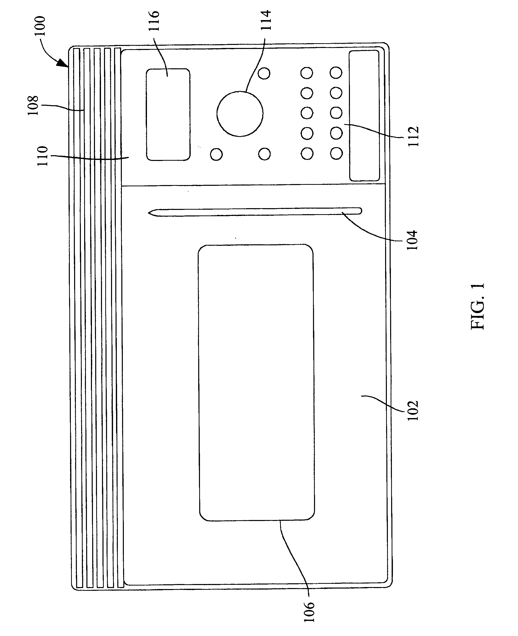
[0016]FIG. 1 is a front view of an over the range type oven 100. Oven 100 includes a frameless glass door 102 having an injection molded handle 104. A window 106 is provided for visualizing food in the oven cooking cavity. Door 102 has an inner metal frame that extends around the door periphery and comprises an RF door cho...


PUM


Abstract

A detection circuit includes a first power line, a first signal conditioning module operationally coupled to the first power line, a neutral line (N) operationally coupled to the first signal conditioning module, a second signal conditioning module operationally coupled to the first power line, a second power line operationally coupled to the second signal conditioning module, and an analog to digital (A/D) converter operationally coupled to the first and the second signal conditioning modules.

Description

BACKGROUND OF THE INVENTION [0001] This invention relates generally to power management systems and methods, and more particularly, to power supply systems and methods for cooking platforms. [0002] There exist different types of cooking platforms which incorporate various appliances that can be activated individually or simultaneously. For example, a typical electric household range includes an oven and generally four surface heating elements. Once the cooking platform is connected within a household, there will be a preset power supply limit available for use by the cooking platform. In some instances, the cooking platform is connected to a nominal 240 volt alternating current (ac) circuit using a neutral wire to create two separate 120 volt circuits internal to the cooking apparatus. The three wires used in 240 volt wiring are commonly referred to L1, L2, and N, where N represents neutral, and wherein L1 and L2 are both 120 volts different from neutral and 240 volts from each othe...

Claims


Application Information

Patent Timeline
IPC IPC(8): F24C7/02F24C7/08G08B21/00H02J3/00H02J4/00H05B6/66H05B6/68
CPCH05B6/666F24C7/087
Inventor ODORCIC, KRESIMIRHORNING, SCOTTJACKSON, TIMOTHY RAYPOWELL, TIMOTHY FRANCISBLANCHARD, CECILIA MARIAKOLLIPARA, MEHER PRASADUSHAH, MARK DILIPTHOMAS, GREGORY MICHAEL
Owner HAIER US APPLIANCE SOLUTIONS INC
Why Eureka
Try Eureka