Transmission arrangement and method for operating an amplifier in a transmission arrangement

a transmission arrangement and amplifier technology, applied in the direction of transmission, amplifiers with semiconductor devices/discharge tubes, gain control, etc., can solve the problems of increasing the space requirement of power amplifiers, unfitting of entire chips, and reducing the linearity of amplifiers

Inactive Publication Date: 2005-11-03
INFINEON TECH AG +1
View PDF20 Cites 80 Cited by
  • Summary
  • Abstract
  • Description
  • Claims
  • Application Information

AI Technical Summary

Benefits of technology

[0011] The present invention is directed to a less expensive and more flexible transmission arrangement over conventional solutions, particularly for mobile radio applications. The invention is preferably intended to be able to be used equally for various modes of operation. The invention also includes a method that allows an amplifier in a transmission arrangement to be operated using simple means.
[0014] In one embodiment the invention contemplates producing the control circuit having the various signals for setting the power amplifier operational mode and the power amplifier in two different semiconductor bodies. This means that the power amplifier can be implemented using the best technology for the respective demand. The control circuit, which particularly contains the supply or bias circuits and the circuits for setting various modes of operation for the power amplifier, is implemented outside of the semiconductor body of the power amplifier and uses the technology that is best for it. The programmable control circuit can thus cover a plurality of modes of operation in the power amplifier in optimum fashion on account of the significantly more powerful digital and / or analog circuits that can be produced. The power amplifier can likewise be designed for a plurality of modes of operation which can be set by the control circuit, which means that it is possible to dispense with additional power amplifier trains in a transmission arrangement.
[0015] The measuring apparatus allows the best setting parameters to be produced for the various modes of operation of the power amplifier. In particular, it is also possible for the measuring apparatus to detect dynamic effects of the power amplifier in the course of operation and for these to be taken into account as appropriate when producing the setting parameters.
[0016] In one embodiment of the invention, the measuring apparatus in the semiconductor body is designed to measure a temperature rise caused by the power amplifier. In another embodiment of the invention, the measuring apparatus is designed to measure a drawn current in the power amplifier. Similarly, the measuring apparatus can measure the gain factor of the power amplifier or the power amplifier output power. The “standing-wave ratio” or the current or voltage amplitudes at the output of the power amplifier is / are also a possible operating parameter for the power amplifier which can be used to set the setting parameters. This allows the linearity of the amplifier to be kept constant, in one example.
[0018] In another embodiment of the invention, the setting parameter for the power amplifier (which setting parameter can be set by the control circuit) comprises the value of the quiescent current in the power amplifier. In addition, the setting parameter may also comprise a setting for the gain factor in the power amplifier or a setting for the output power in the power amplifier. Similarly, the control circuit can be designed to set a temperature dependency for the quiescent current. The term quiescent current includes, inter alia, the output quiescent current from the amplifier, but also an electrical variable that sets an operating point for the amplifier. In another embodiment, the control circuit comprises a detection device that evaluates the information transmitted by the measuring apparatuses. If a predetermined limit value is exceeded, the detection device is designed to output a signal for disconnecting the power amplifier. Preferably, the detection device thus forms a protective circuit that protects the power amplifier against overvoltage, excessively high current or a damaging standing-wave ratio.

Problems solved by technology

When expensive substrates such as GaAs or InP are chosen for the implementation, the bias or pilot circuit is thus also produced using expensive and complex technology.
This increases the space requirement for a power amplifier.
If the bias circuit fails then the entire chip is unfit, and if there is a change in the demand on the power amplifier then it is very frequently necessary to design and process a new bias and control circuit and hence a completely new power chip.

Method used


Image

  • Transmission arrangement and method for operating an amplifier in a transmission arrangement
  • Transmission arrangement and method for operating an amplifier in a transmission arrangement
  • Transmission arrangement and method for operating an amplifier in a transmission arrangement

Examples


Embodiment Construction

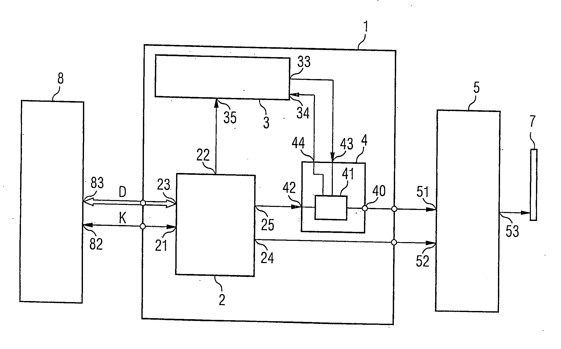
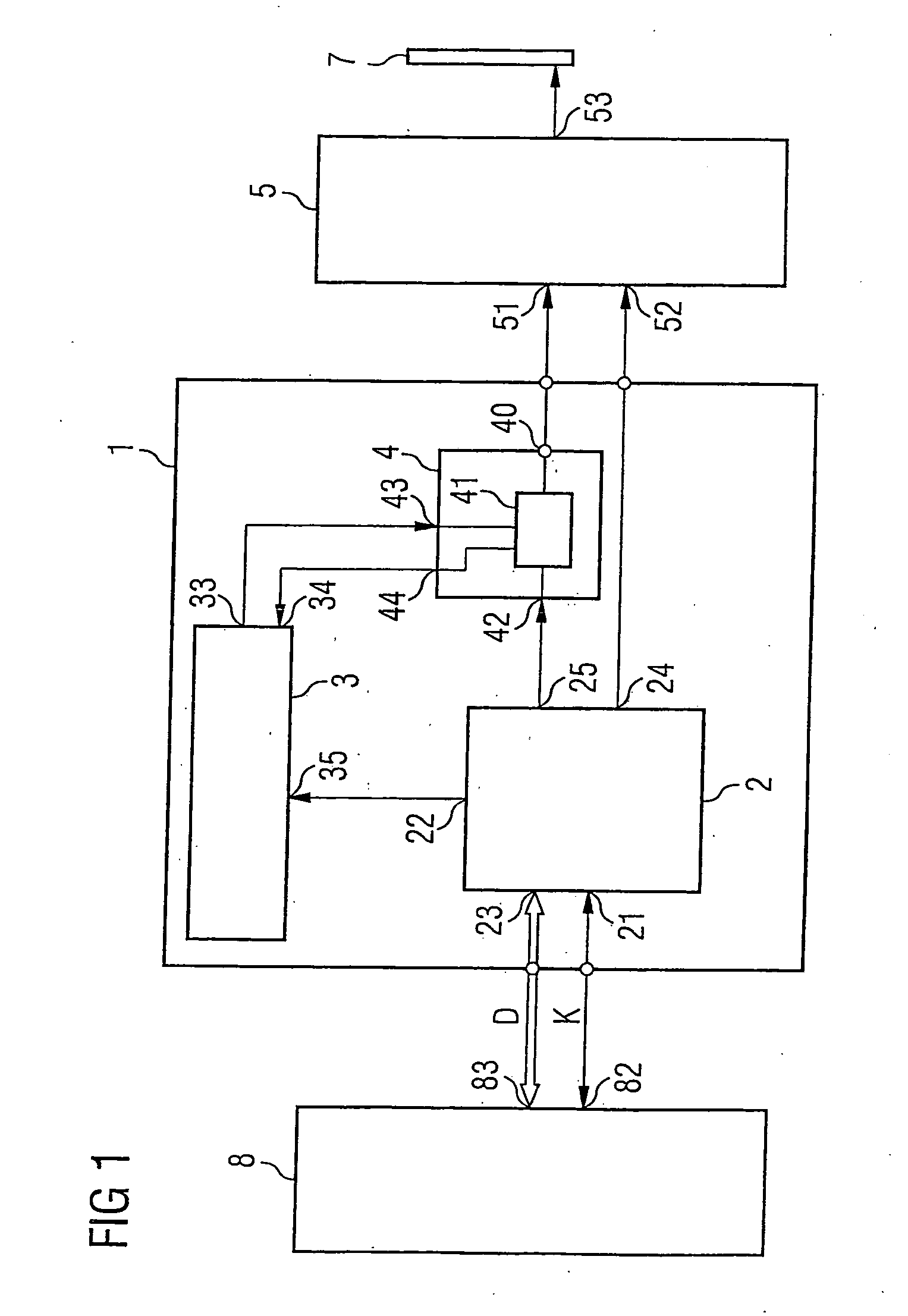
[0028]FIG. 1 shows an inventive transmission arrangement 1 in a transmission path. The transmission path is part of a mobile communication appliance (not shown for reasons of clarity) that can send and receive in accordance with a plurality of mobile radio standards. The mobile radio standards make different demands on the transmission path. Whereas, by way of example, the GSM mobile radio standard involves a signal for transmission always being transmitted with the same amplitude during the transmission operation, the signal for transmission is amplitude-dependent in the WCDMA mobile radio standard. The demands regarding linearity of the gain of a power amplifier in the transmission path are therefore significantly higher.

[0029] Besides the inventive transmission arrangement 1, the transmission path also contains a baseband unit 8. The baseband unit 8 has an output 83 for a data stream D, which is connected to an input 23 on a transmitter circuit 2 in the inventive transmission ar...


PUM


Abstract

A transmission arrangement includes a transmitter circuit for subjecting signals for transmission to signal conditioning, the signal output of said transmission arrangement being connected to a power amplifier. The power amplifier is produced in a semiconductor body and has at least one mode of operation that is characterized by at least one adjustable setting parameter. Outside of the semiconductor body, there is a programmable control circuit which is designed to send setting signals to the power amplifier in order to set the at least one adjustable setting parameter. The control circuit and the power amplifier are thus of separate design and can each be produced independently using the best technology.

Description

REFERENCE TO RELATED APPLICATIONS [0001] This application claims the benefit of the priority date of German application DE 10 2004 017 528.4, filed on Apr. 8, 2004, the contents of which are herein incorporated by reference in its entirety. FIELD OF THE INVENTION [0002] The invention relates to a transmission arrangement and a method for operating an amplifier in a transmission arrangement. BACKGROUND OF THE INVENTION [0003] Transmission arrangements are used for applications in the field of communication within mobile communication appliances. In order to allow diverse applications in modern mobile communication appliances, it is necessary for the transmission unit to be able to cover a plurality of different modes of operation for different communication standards. Examples of different modes of operation are found in the various mobile radio standards, such as GSM / EDGE, GPRS, UMTS / WCDMA, 802.11a / b, GPS and others. [0004] The various modes of operation differ, inter alia, in the o...

Claims


Application Information

Patent Timeline
Patent Type & Authority Applications(United States)
IPC IPC(8): H03F1/06H03F3/45H03G3/00H04B1/04H04B1/40
CPCH03F1/0205H04B2001/0408H04B1/406H03F1/06H03F3/24
Inventor MULLER, JAN-ERIK
Owner INFINEON TECH AG
Why Eureka
Try Eureka