Current limitation in an inductance with a limit current adaptation

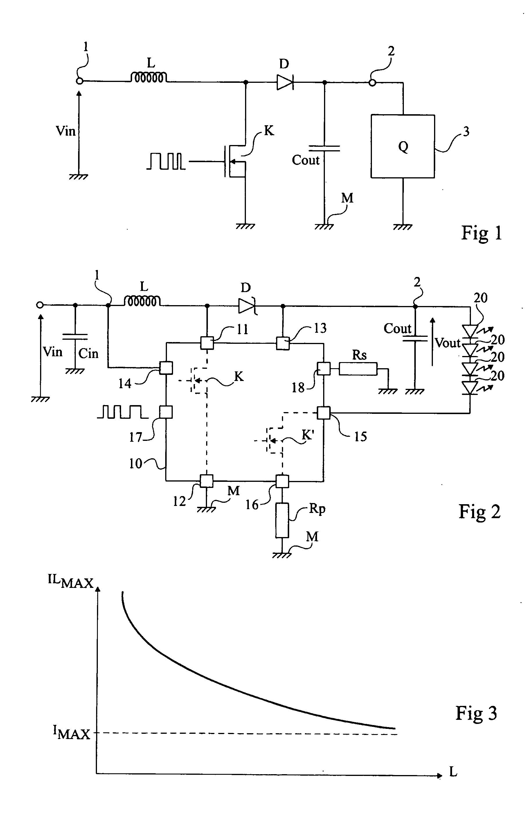
a current adaptation and current limitation technology, applied in the field of circuits, can solve the problems of insufficient utilization of capacity and insufficient utilization of inductance lb>2/b> having a limiting current ilmax greater than current imax, and achieve the effect of improving the utilization of performan

Active Publication Date: 2005-06-23
STMICROELECTRONICS SRL
View PDF5 Cites 1 Cited by
  • Summary
  • Abstract
  • Description
  • Claims
  • Application Information

AI Technical Summary

Benefits of technology

[0017] One aspect of the present invention aims at improving the exploitation of the performances of an inductance while protecting it.
[0019] A further aspect of the present invention also aims at providing a solution unresponsive to possible variations of supply voltage Vin, especially when this voltage corresponds to a battery voltage.
[0020] A still further aspect of the present invention also aims at providing an integrated circuit for controlling a switch to be connected to an inductance, which has a current-limiting function therein, without requiring any external resistor for parameterizing the limiting current value.

Problems solved by technology

A disadvantage of such a solution is that circuit 10 is then dedicated to an inductance L or, to stand several inductances of different values, requires setting of a minimum threshold while some inductances could stand higher currents.
A disadvantage of this solution is that it requires a terminal (18) of additional connection of integrated circuit 10 as well as an external resistor.
As a result, according to the inductance connected to circuit 10, its capacities are not fully exploited.
As illustrated in the right-hand portions of the timing diagrams, this results in inductance L2 having its limiting current ILmax greater than current Imax is not fully exploited.

Method used


Image

  • Current limitation in an inductance with a limit current adaptation
  • Current limitation in an inductance with a limit current adaptation
  • Current limitation in an inductance with a limit current adaptation

Examples


Embodiment Construction

[0044] The following discussion is presented to enable a person skilled in the art to make and use the invention. Various modifications to the embodiments will be readily apparent to those skilled in the art, and the generic principles herein may be applied to other embodiments and applications without departing from the spirit and scope of the present invention. Thus, the present invention is not intended to be limited to the embodiments shown, but is to be accorded the widest scope consistent with the principles and features disclosed herein.

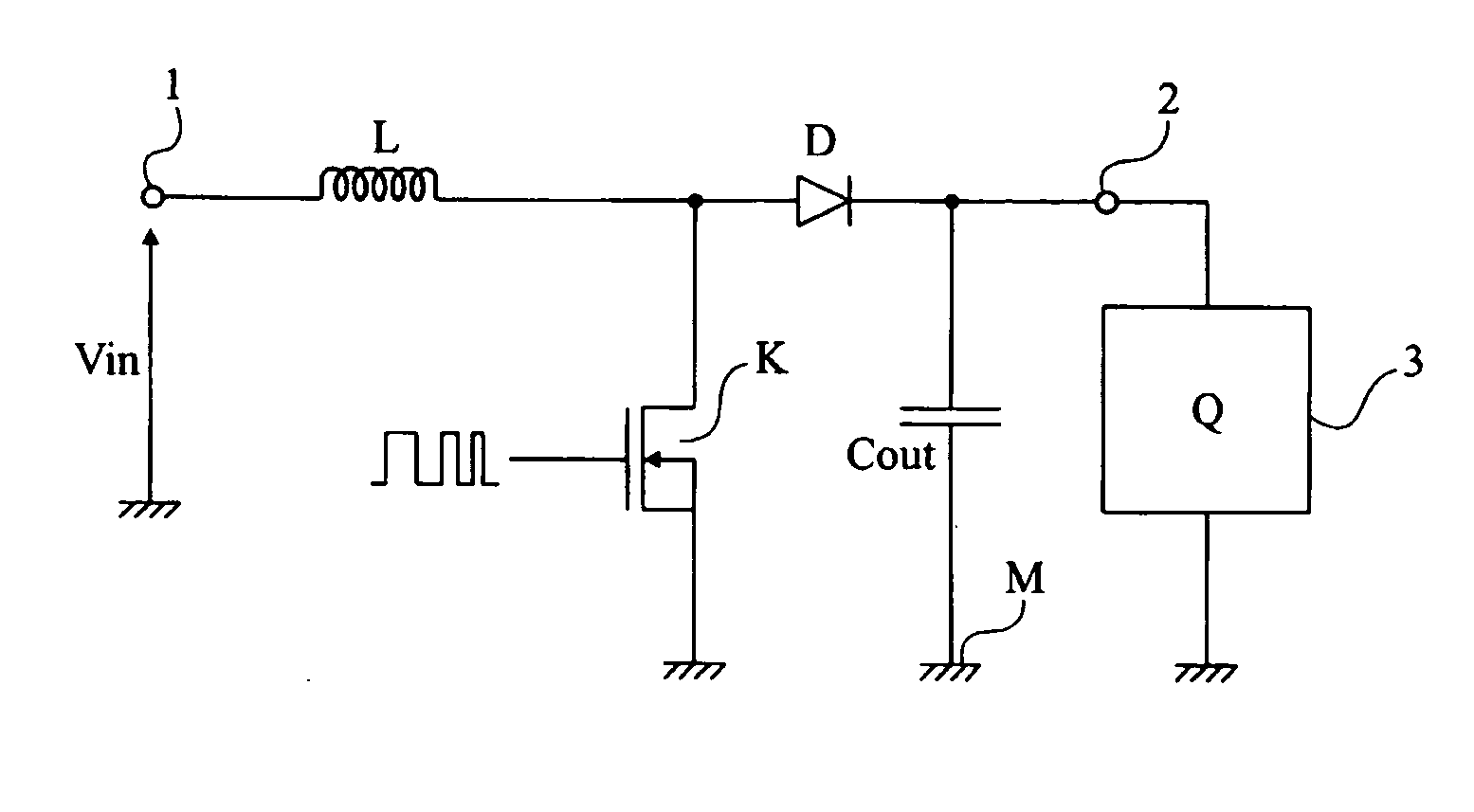
[0045] The same elements have been designated with the same reference numerals in the different drawings. For clarity, only those elements which are necessary to the understanding of the present invention have been shown in the drawings and will be described hereafter. In particular, the circuit for generating the control pulses of switch K with a control of the output voltage has not been detailed and is no object of the present invention, t...


PUM


Abstract

A method and a circuit for limiting the current in an inductance, comprising means for interrupting the power storage in the inductance at the end of a delay triggered by the current in the inductance.

Description

PRIORITY CLAIM [0001] This application claims priority from French patent application No. 03 / 51072, filed Dec. 16, 2003, which is incorporated herein by reference. BACKGROUND OF THE INVENTION [0002] 1. Field of the Invention [0003] Embodiments of the present invention relate to the field of circuits for protecting an inductance so that the current flowing through it does not exceed its saturation current, and relate to any system in which the current is desired to be limited in an inductance. An example application for embodiments of the present invention is the field of power converters (step-up or step-down) in which a switch controlling the current in an inductance is controlled by a train of pulses, for example, modulated in width (PWM), in frequency (FWM), etc. [0004] 2. Discussion of the Related Art [0005]FIG. 1 very schematically shows a conventional example of a step-up converter. [0006] Such a converter uses an inductance L in series with a diode D between a terminal 1 for ...

Claims


Application Information

Patent Timeline
Patent Type & Authority Applications(United States)
IPC IPC(8): H02H9/02H02M1/00H02M3/02H02M3/156
CPCH02H9/02H02M3/156H02M1/32
Inventor FLORENCE, ARNAUDHEURTIER, JEROMEGALTIE, FRANCK
Owner STMICROELECTRONICS SRL
Why Eureka
Try Eureka