Corrosion monitoring system, optical corrosion probe, and methods of use

a corrosion monitoring and optical corrosion technology, applied in the direction of optical radiation measurement, fluorescence/phosphorescence, instruments, etc., can solve the problems of significant repair costs, possible other dangers, and very real problems of corrosion, and achieve the effects of improving the accuracy of inspection and testing

Active Publication Date: 2005-06-23
CUSTOM SENSORS & TECH INC
View PDF16 Cites 22 Cited by
  • Summary
  • Abstract
  • Description
  • Claims
  • Application Information

AI Technical Summary

Benefits of technology

[0015] To deal with these and other problems in the art, described herein are optical corrosion monitoring and detection systems as well as methods to detect and monitor corrosion under process conditions in real time using electromagnetic radiation, particularly light. That is, a corrosion monitoring system such as those described herein can measure (or more accurately approximate

Problems solved by technology

Corrosion presents a very real problem in systems which store, use, or transport corrosive materials.
If ignored, corrosion can eventually damage the piping or tank to a point where leaks or failures occur resulting in significant repair costs and possible other dangers.
While corrosion can occur in any type of piping or tank, it is particularly problematic in underground, undersea, or other difficult to access areas.
Pipes susceptible to corrosion can be carrying crude oil, water, steam, or any other fluids or gases which are known to be corrosive to the metals of which piping is usually constructed.
These pipes can also be corroded by the materials (such as water or earth) that they are placed within.
Further, failure of these pipes can result in danger to occupants of buildings, can result in contamination of groundwater or similar resources, or can cause environmental damage.
While this type of control can be effective, it is often very expensive.
Further, coatings will often mechanically wear in a flow or may develop cracks over time which can lead to failure.
Further, there are relatively few materials which are able to resist the wide variety of potentially reactive materials which may be in a process stream.
Because material selection is necessarily imperfect and quite expensive, the most common method for attempting to control corrosion is through the addition of corrosion inhibiting or control chemicals to the process stream which is within the pipe or tank.
This method also is quite expensive due to maintenance down cycles and the ongoing costs associated with the required chemicals.
Further, the method can actually create additional problems as the corrosion inhibiting chemicals may need to later be filtered out and may prove damaging to other systems which come into contact with the process stream.
Additionally, monitoring allows the operator to schedul

Method used


Image

  • Corrosion monitoring system, optical corrosion probe, and methods of use
  • Corrosion monitoring system, optical corrosion probe, and methods of use
  • Corrosion monitoring system, optical corrosion probe, and methods of use

Examples


Embodiment Construction

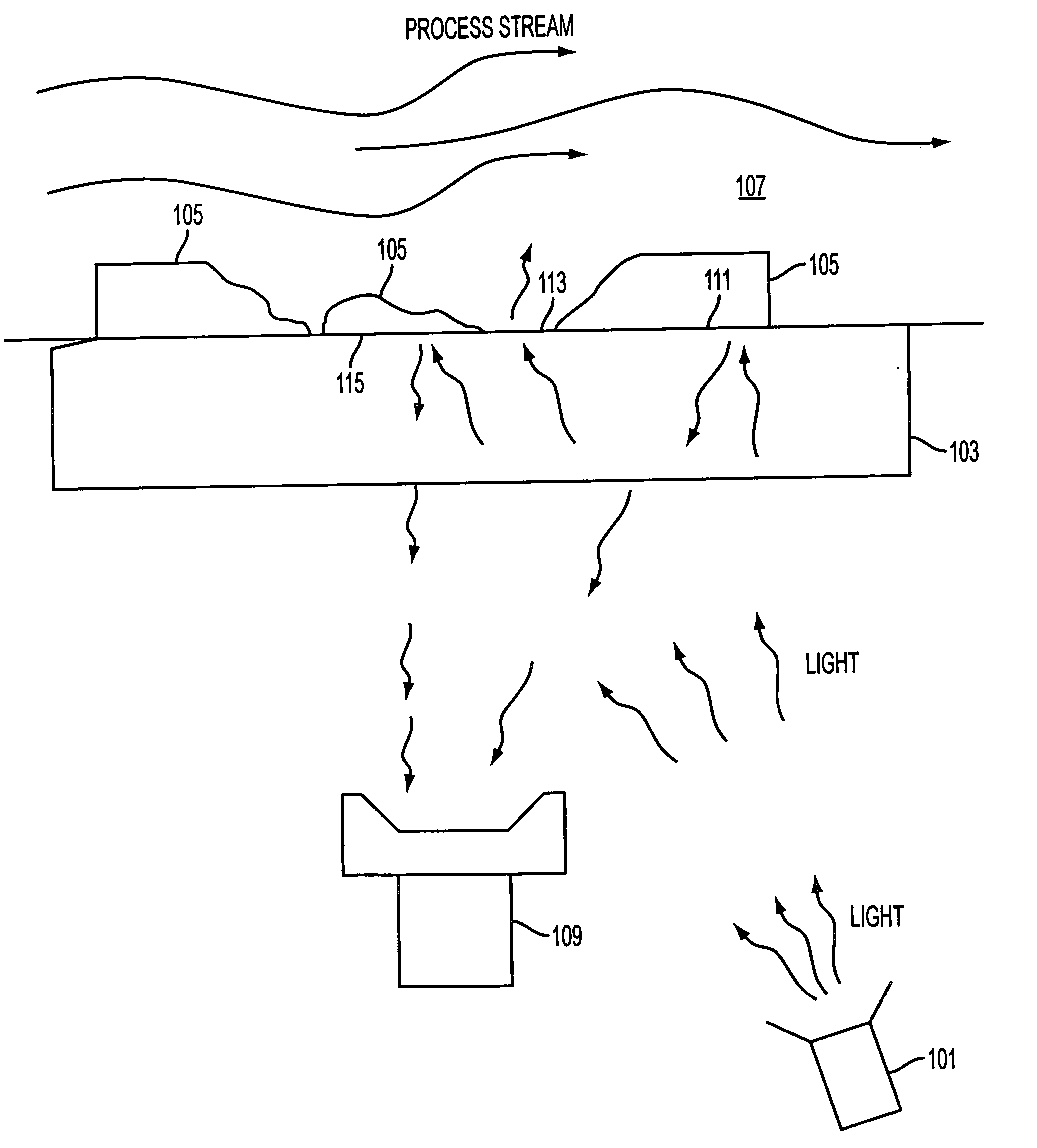
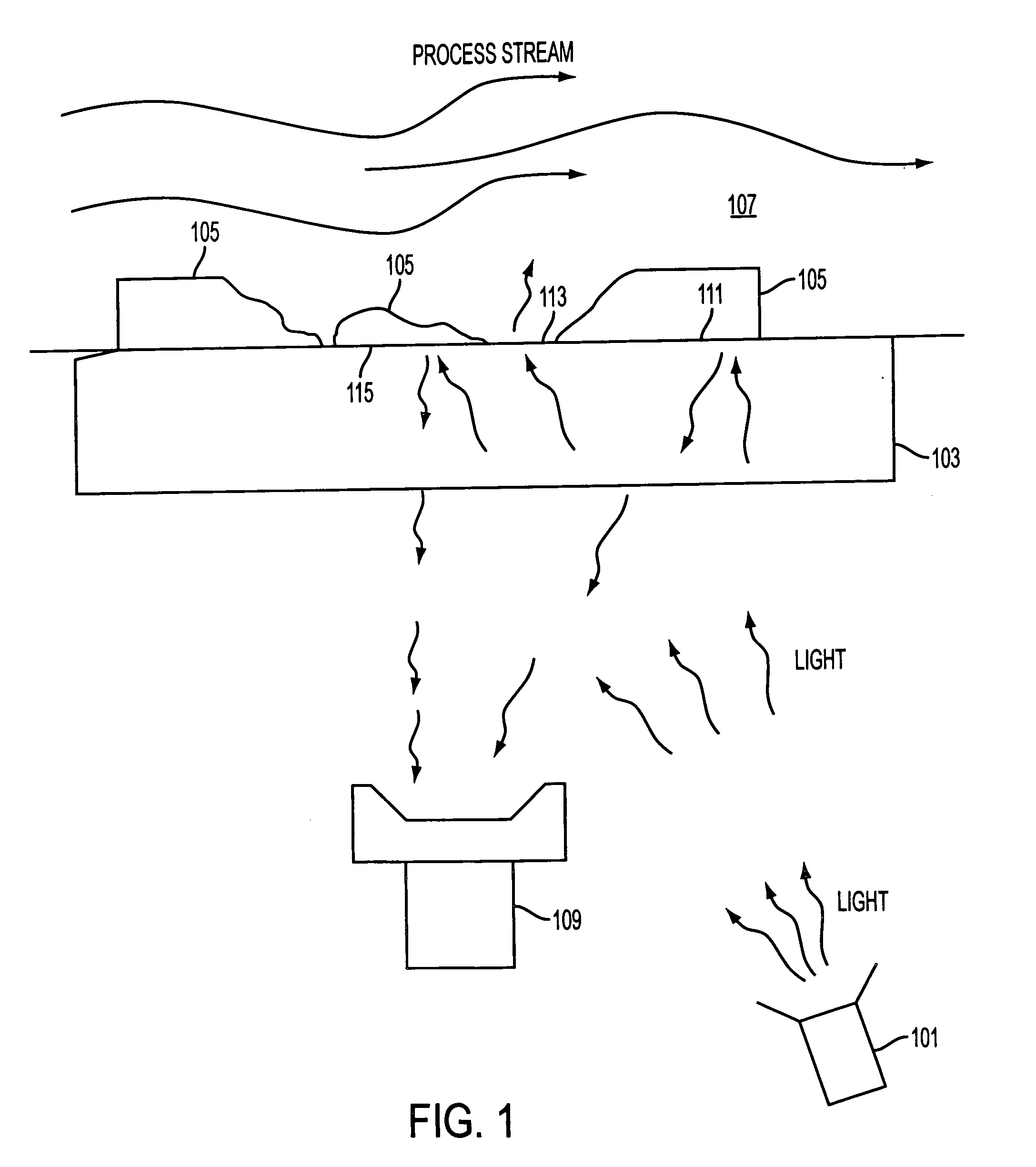
[0034] In a general overview, an embodiment of the corrosion monitoring system preferably operates on the concept of reflectance from a surface. The embodiments discussed herein presume that the corrosion causing material is a fluid and that the fluid is within a section of pipe whether in a stationary or flowing state. For ease of description, the system encasing the process stream will often be referred to as a pipe, however, this term is not intended to be limiting to particular vessels for holding or transporting the process stream. The corrosion caused by the fluid's interaction with the material of the vessel is the corrosion which is desired to be monitored or detected. The fluid in the vessel being monitored is referred to as a process stream. The term “process stream” is used because in most situations that fluid will be flowing or moving in the pipe. However, the term is in no way intended to require that the fluid be moving. Further, while the stream will generally be pre...


PUM


Abstract

Optical corrosion monitoring and detection systems as well as methods to detect and monitor corrosion under process conditions and generally in real time using electromagnetic radiation, particularly light. The systems generally provide for incident light to be allowed to reflect from a coating which is exposed to the corroding action of the process stream. As the coating is corroded, the intensity, or other function, of the incident light is changed and this change is detected and used to extrapolate a level of corrosion.

Description

CROSS REFERENCE TO RELATED APPLICATION(S) [0001] This application claims priority to U.S. Provisional Patent Application Ser. No. 60 / 528,379 filed Dec. 10, 2003, the entire disclosure of which is herein incorporated by reference. BACKGROUND OF THE INVENTION [0002] (1) Field of the Invention [0003] The present invention pertains to probes for monitoring corrosion. Particularly for monitoring corrosion within pipes or tanks by utilizing electromagnetic radiation such as light. [0004] (2) Background of the Invention [0005] Corrosion presents a very real problem in systems which store, use, or transport corrosive materials. It is particularly important in piping or storage systems where corrosive materials, such as liquids or gases being stored or transported, may be in contact with the interior surface of a pipe or tank for an extended period of time, and where damage from corrosion may not be readily visible. If ignored, corrosion can eventually damage the piping or tank to a point wh...

Claims


Application Information

Patent Timeline
IPC IPC(8): G21C9/00
CPCG01N21/55G01N2021/8427G01N21/8507G01N21/64G01N21/274
Inventor PONSTINGL, MICHAELFORD, JESS V.JOHNSON, ANTHONY
Owner CUSTOM SENSORS & TECH INC
Why Eureka
Try Eureka