Modular fiber optic connector system

Inactive Publication Date: 2005-06-23
AMPHENOL CORP
View PDF10 Cites 63 Cited by
  • Summary
  • Abstract
  • Description
  • Claims
  • Application Information

AI Technical Summary

Benefits of technology

[0022] It is an object to provide an optical interconnection sys

Problems solved by technology

The system might be too big to fit in a single enclosure or might require subassemblies located in physically separate locations.
For example, data storage farms are made of interconnected storage units because it is likely that one unit containing all the necessary circuitry would be too large to easily fit within a single housing.
Several problems exist with optical interc

Method used


Image

  • Modular fiber optic connector system
  • Modular fiber optic connector system
  • Modular fiber optic connector system

Examples


Embodiment Construction

[0037] This invention is not limited in its application to the details of construction and the arrangement of components set forth in the following description or illustrated in the drawings. The invention is capable of other embodiments and of being practiced or of being carried out in various ways. Also, the phraseology and terminology used herein is for the purpose of description and should not be regarded as limiting. The use of “including,”“comprising,” or “having,”“containing”, “involving”, and variations thereof herein, is meant to encompass the items listed thereafter and equivalents thereof as well as additional items.

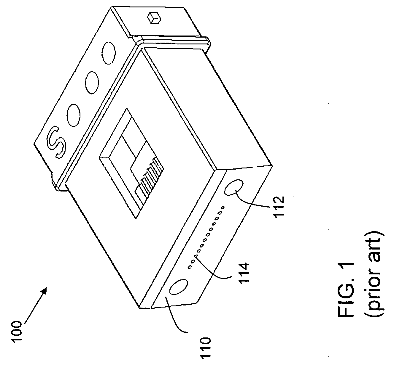
[0038]FIG. 1 shows a multi-fiber ferrule 100, as is known in the art. Ferrule 100 has a mating face 110. Mating face 110 includes alignment features, such as holes 112. Fiber ends project through holes 114, that are precisely positioned relative to alignment holes 112. In operation, ferrule 100 would be held within a connector. That connector would mate with ...


PUM


Abstract

An optical fiber interconnection system with a small number of modular components that can be configured for simple construction in many configurations. The system includes connector housings. Optical fibers are installed into the housings on ferrule carriers. The housings are brought together in adapters. Different styles of adapters are available for different applications, such as panel or backplane configurations. However, the same housing and ferrule carriers can be used in any style of adapter. Also, different ferrule carriers are provided for single fiber ferrules and multi-fiber ferrules. Either style of ferrule carrier can be used in a housing and adapter. A ferrule carrier for single fiber ferrules can be modified to provide fine alignment features with the addition of a cap, allowing the same style ferrule carrier to be used in both halves of a mated connector assembly.

Description

BACKGROUND OF INVENTION [0001] 1. Field of Invention [0002] This invention relates generally to electronic systems and more specifically to electronic systems using optical fibers to carry data between components of the system. [0003] 2. Discussion of Related Art [0004] Many types of electronic systems are known. Common examples of electronic systems are computers, routers and telecommunications switches. Complex electronic systems have long been built as subassemblies that are then integrated into an overall system. Integration requires that data be passed between subassemblies. [0005] Traditionally, integration of subassemblies has included making connections for electrical signals to carry data between the subassemblies. In some systems, printed circuit boards, sometimes called backplanes, are used to carry electrical signals between subassemblies. Backplanes are usually built as printed circuit boards. Conductive traces within the board carry electrical signals and electrical co...

Claims


Application Information

Patent Timeline
IPC IPC(8): G02B6/36G02B6/38
CPCG02B6/3821G02B6/3825G02B6/3897G02B6/3879G02B6/3885G02B6/3869G02B6/3893
Inventor KIANI, SEPEHRROTH, RICHARD F.
Owner AMPHENOL CORP
Why Eureka
Try Eureka