Implant positioning device and method

a positioning device and implant technology, applied in the field of dentistry, can solve the problems of inability to control the location of the implant, the design of the prosthesis may not be ideal in terms of strength, esthetic appearance or biological response, and the template provides only a rough or imprecise guide, etc., and achieves the effect of expanding the hol

Inactive Publication Date: 2005-06-23
CARMICHAEL ROBERT P +1
View PDF7 Cites 17 Cited by
  • Summary
  • Abstract
  • Description
  • Claims
  • Application Information

AI Technical Summary

Problems solved by technology

One of the problems that can arise in this situation is that the template provides only a rough or imprecise guide as to where the dentist should place the implant.
Thus, because the dentist is given some leeway in deciding where the implant is to be placed, the location of the implant is not controlled and may not reflect the position intended by the laboratory.
Accordingly, the design of the prosthesis may be non ideal in terms of strength, esthetic appearance or the biological response it provokes.

Method used


Image

  • Implant positioning device and method
  • Implant positioning device and method
  • Implant positioning device and method

Examples


Embodiment Construction

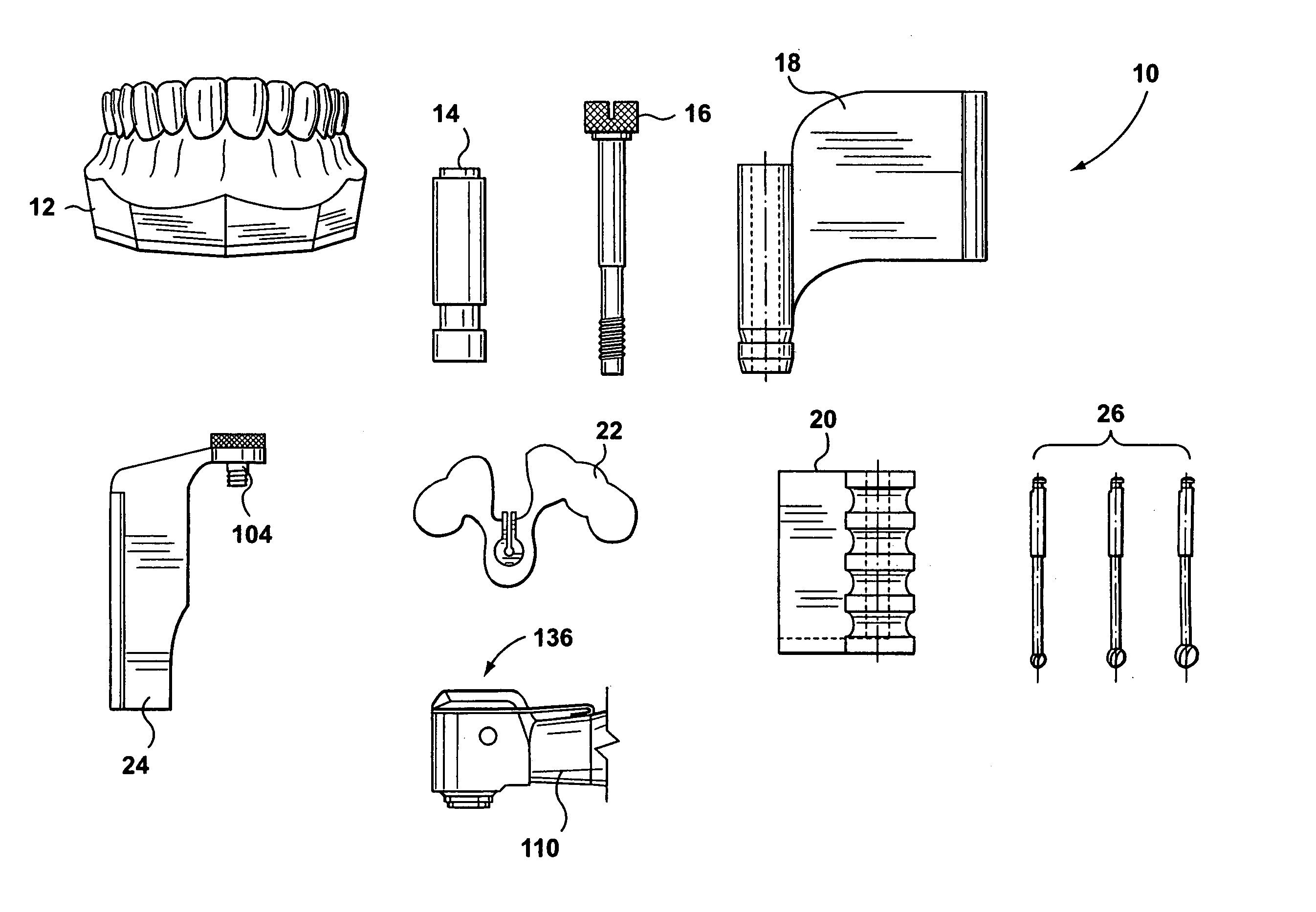
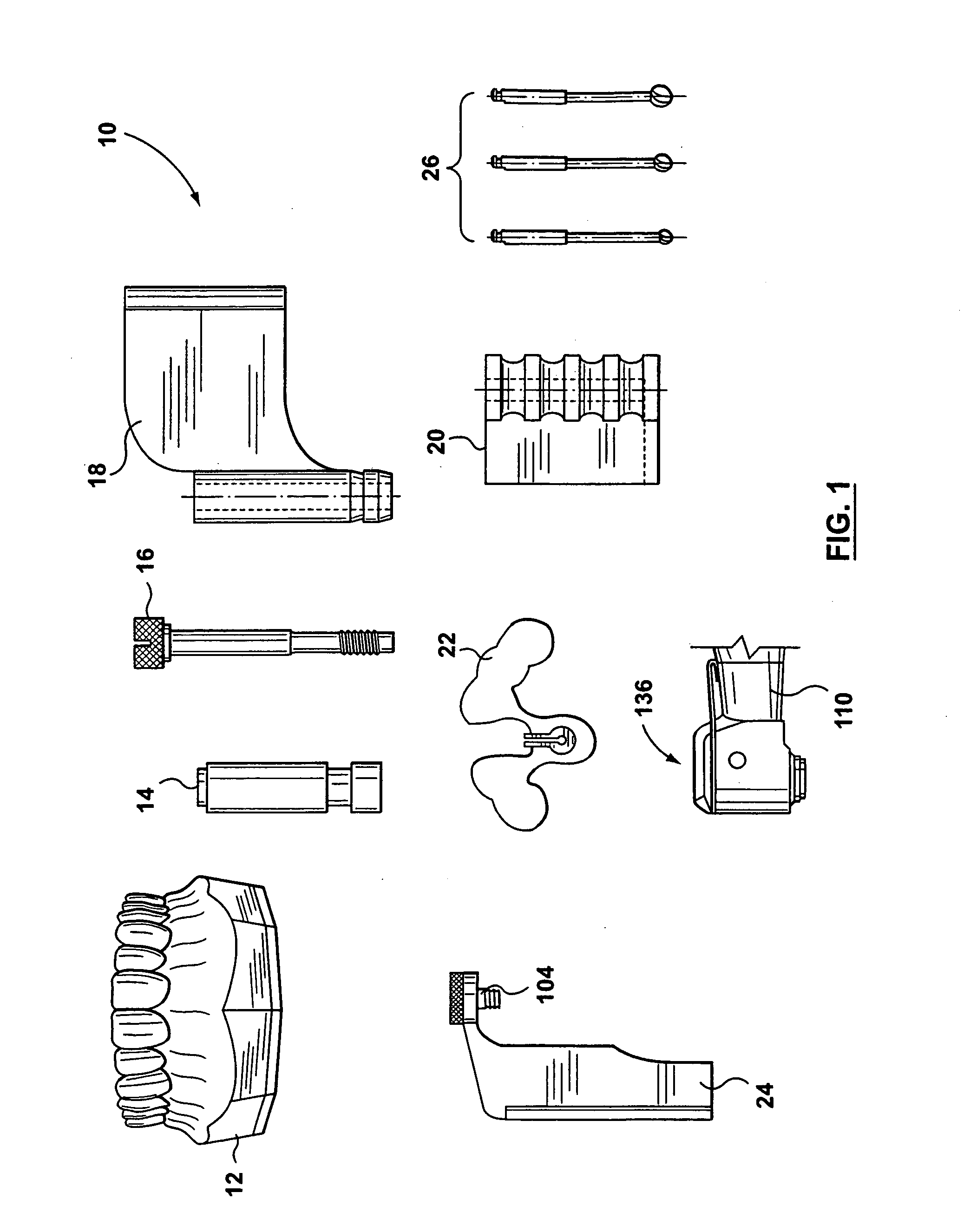
[0034]FIG. 1 illustrates a kit of parts that is useful in carrying out the method in accordance with a preferred embodiment of the invention. The kit of parts is indicated generally at 10. The kit includes a cast dental arch 12, a proxy implant 14, a retainer screw 16, a stent alignment arm 18, a locating barrel 20, a stent 22, a drill alignment arm 24 and a plurality of drills 26. The kit is used with a custom drill head 110 which may be part of the kit or dealt with separately.

[0035] The kit of part 10 includes all the pieces required to use the invention described herein in accordance with the preferred embodiment. The persons involved in using the invention include the dental professional, the support staff in the dental professionals' office, dental laboratory professionals and support staff and manufacturers of the components of the kit of parts. Not all parts need be formed, manufactured or used by all persons involved. However, the kit illustrates all components which are u...


PUM


Abstract

The invention includes a method and apparatus to guide a dental drill to drill a bore into which a dental implant may be inserted at a particular axis. The dentist first takes an impression of a selected patient's dental arch. The cast dental arch is then formed from the impression. A dental professional then determines the desired location of the desired axis. A proxy implant having a proxy axis is placed in the cast dental arch with the proxy axis co-incident with the desired location of the desired axis. A stent is then formed of the tooth crowns from the cast dental arch. The stent has incorporated into it a locating barrel. A drill head with a drill alignment arm is provided to the dentist for fixation to a dental drill hand piece. The kit of parts provided to the dentist includes the stent with its incorporated locating barrel. The drill alignment arm provided to the dentist for attachment to the drill head and a plurality of drills. By using the stent with its incorporated locating barrel, the dentist's drill is guided into the desired location by interaction of the pin of the drill alignment arm with the locating barrel in the stent. By additionally controlling the length of the drills, the location, axis and depth of the drill hole made by the dentist will exactly coincide with the designed location, depth and orientation of the implant.

Description

[0001] This application is a divisional of U.S. application Ser. No. 10 / 086,859 filed Mar. 4, 2002.FIELD OF THE INVENTION [0002] This invention relates to the field of dentistry. In particular, the invention relates to the positioning of dental implants. BACKGROUND OF THE INVENTION [0003] Dental implants are commonly use in dental procedures. Often when a tooth has been removed, an implant is placed in the jaw bone and a dental prosthesis is then positioned using the implant. The implant is incorporated in the bone material and provides a suitable anchor for various types of dental prostheses. [0004] Typically, when a dental implant is to be installed, a dentist prepares a cast of the patient's dental arch. That cast is then forwarded to a dental lab for creation of a suitable template. When the lab has determined the appropriate implant location to be used given the conditions of the patient's dental arch, the lab forwards a suitable template to the dentist. The dentist, guided by ...

Claims


Application Information

Patent Timeline
Patent Type & Authority Applications(United States)
IPC IPC(8): A61C8/00A61C1/08
CPCA61C1/084
Inventor CARMICHAEL, ROBERT P.SANDOR, GEORGE K. B.
Owner CARMICHAEL ROBERT P
Why Eureka
Try Eureka