
System and method for RF power control

a power control and radio frequency technology, applied in power management, gain control, wireless communication, etc., can solve the problems of insufficient power retention of current wlan transmitters, people tend to consume a lot of information, and inability to keep transmitting power at a fixed level

Inactive Publication Date: 2005-06-23
ACCTON TECHNOLOGY CORPORATION
View PDF3 Cites 33 Cited by
  • Summary
  • Abstract
  • Description
  • Claims
  • Application Information

AI Technical Summary

Benefits of technology

[0010] An object of the present invention is to provide a system and method for RF power control, which can adjust the power supply therein according to data rates for transmitting RF signals in good quality.
[0011] Another object of the present invention is to provide a system and method for RF power control, which can avoid possible signal quality degradation resulted from RF power amplification.
[0012] Another object of the present invention is to provide a system and method for RF power control, which can bring an electricity-saving effect to a transmitting device therein.

Problems solved by technology

In the Internet era, people tend to consume a lot of information rapidly.
However, the transmitting power cannot be retained in a fixed level while the data rate is increasing.
Therefore, the fixed power supply or the fixed bias source would cause the power inadequacy of transmitters of the current WLAN applications.
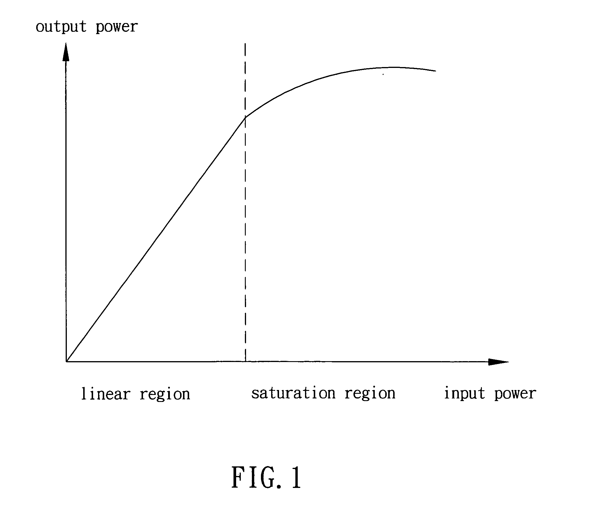
Although the increase of the RF input power could extend the transmission distance, the power-amplifying unit may operate in the saturation region, result in a higher data error rate and thus lower the signal quality.
On the other hand, the RF input power or the gain of the power-amplifying unit may be decreased to preserve the signal quality, nevertheless, the output power cannot be reinforced if the provided power is fixed.
Moreover, if a fixed high power supply is employed, then it will bring power waste when the data rate is low.
Many WLAN applications use batteries for power provision, and the power waste would lower the battery duration and then impact the performance of these applications.
In sum, the drawbacks of using a fixed power supply or a fixed bias source for power amplification of RF signal transmission include: (1) the lowered transmitting power and shortened transmission distance, or the lowered data rate and decreased throughput; (2) the degraded signal quality while preserving the transmitting power; and (3) the power waste when the data rate is low.

Method used


Image

  • System and method for RF power control
  • System and method for RF power control
  • System and method for RF power control

Examples


Embodiment Construction

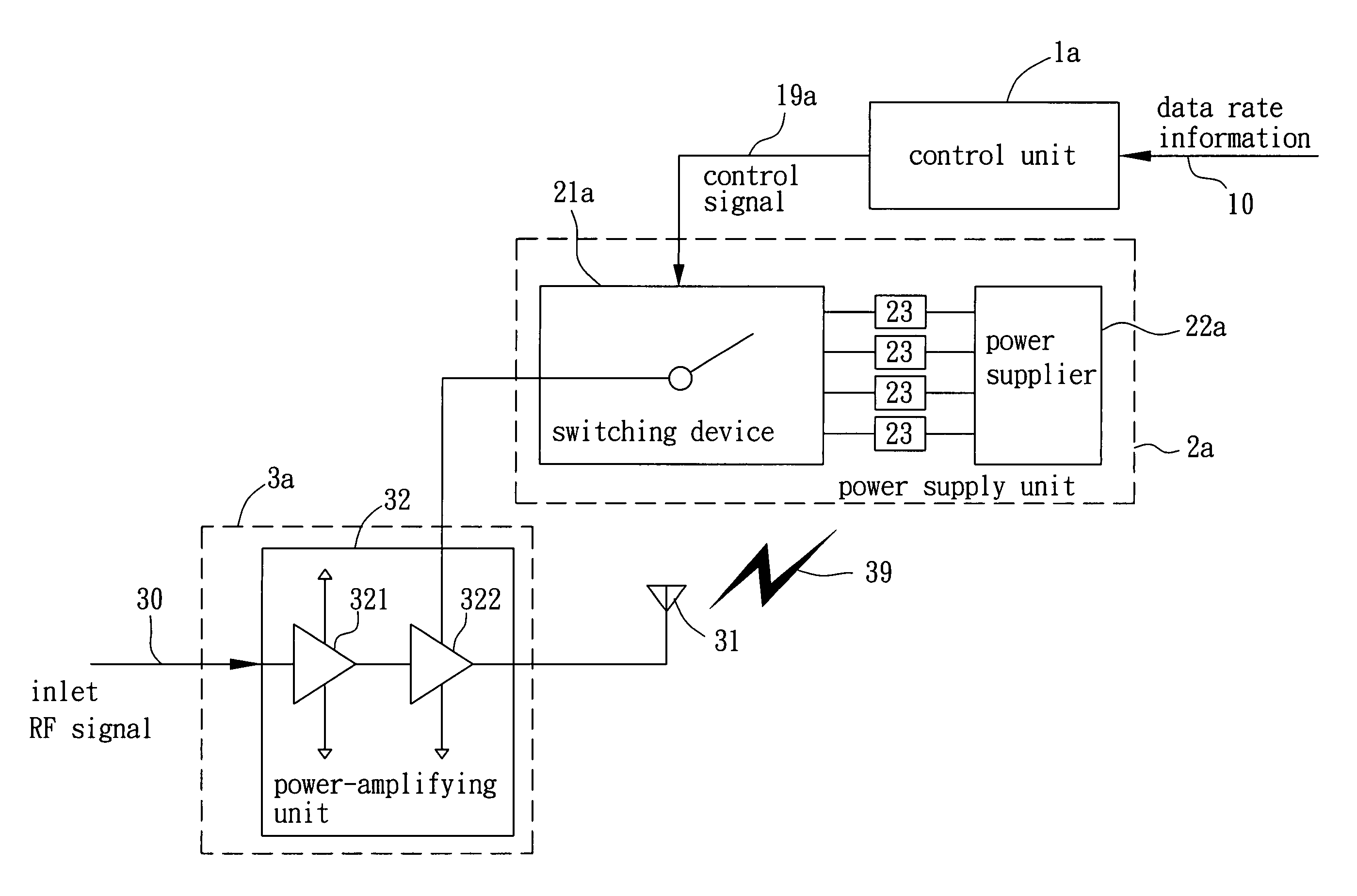
[0019] The present invention can provide a flexible power scheme by adjusting the power supply for RF power amplification according to the data rate. A detailed description of the present invention is provided below with preferred embodiments and appended drawings.

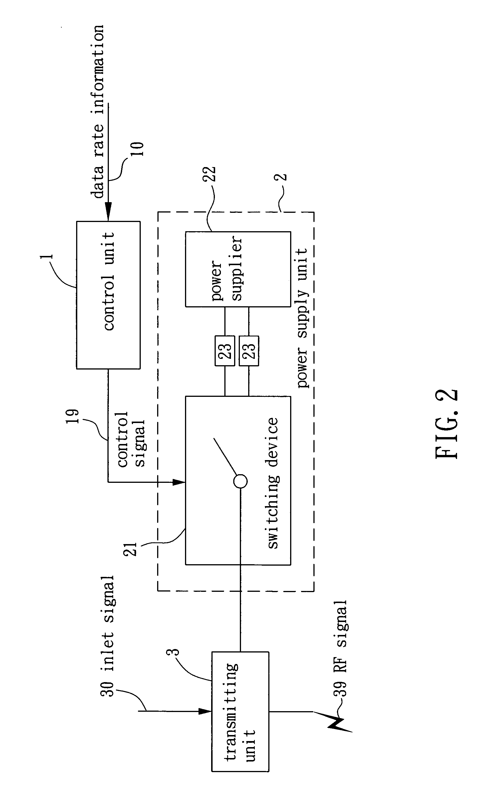
[0020]FIG. 2 is a block diagram showing a preferred embodiment of the system for RF power control according to the present invention. As shown in FIG. 2, the system includes a control unit 1, a power supply unit 2 and a transmitting unit 3. The control unit 1 generates a control signal 19 according to data rate information 10. The data rate information 10 can be a data rate or any signal presenting the data rate. The control unit 1 may include a processor (not shown) to assign the data rate information 10 to a group in terms of a rate range, such as 0-20 Mbps, 20-40 Mbps, 40-60 Mbps, etc. The processor then outputs the control signal 19 containing information, such as a data rate indicator or an index, for indicating the ...


PUM


Abstract

The present invention provides a system and method for radio frequency (RF) power control that can adjust and transmit the RF power to the transmitting device according to the data rate under which the RF signal is going to transmit.

Description

BACKGROUND OF THE INVENTION [0001] (a). Field of the Invention [0002] The present invention relates in general to radio frequency (RF) power control, and more particularly to a system and method that adjusts the power supply according to a data rate for transmitting RF signals in good quality. [0003] (b). Description of the Prior Arts [0004] In the Internet era, people tend to consume a lot of information rapidly. And along with the progress of wireless communication technology, people also want to be freed from the limit of wire connections. Wireless local area network (WLAN), combing the network and wireless communication technologies, is then an ideal solution for these needs. [0005] However, in current WLAN applications, a fixed power supply or a fixed bias source is used for RF power amplification. To achieve the goal of real-time communication, a high data rate is needed. However, the transmitting power cannot be retained in a fixed level while the data rate is increasing. Whe...

Claims


Application Information

Patent Timeline
Patent Type & Authority Applications(United States)
IPC IPC(8): H03G3/00H04B1/04H04B7/005
CPCH03G3/004H04W52/267H04B2001/0416
Inventor LIU, I-RU
Owner ACCTON TECHNOLOGY CORPORATION
Learn More