RF transmitter and receiver front-end

a transmitter and receiver technology, applied in the field of wireless communication systems, can solve the problem of inacceptable channel switching technique of 802.11a receivers by adjusting local oscillation as previously described

Inactive Publication Date: 2005-06-23
VIXS SYSTEMS INC
View PDF13 Cites 35 Cited by
  • Summary
  • Abstract
  • Description
  • Claims
  • Application Information

AI Technical Summary

Benefits of technology

[0006] The fast channel switching radio frequency receiver or transmitter of the present invention substantially meets these needs and others. In one embodiment, a radio frequency receiver front-end includes a low noise amplifier, a mixing stage, and a selectable channel filter. The low noise amplifier is operably coupled to amplify inbound RF signals to produce amplified inbound RF signals. The mixing stage is operably coupled to mix amplified inbound RF signals with a 1st local oscillation to pr...

Problems solved by technology

As such, adjusting the local oscillation as previously described i...

Method used


Image

  • RF transmitter and receiver front-end
  • RF transmitter and receiver front-end
  • RF transmitter and receiver front-end

Examples


Embodiment Construction

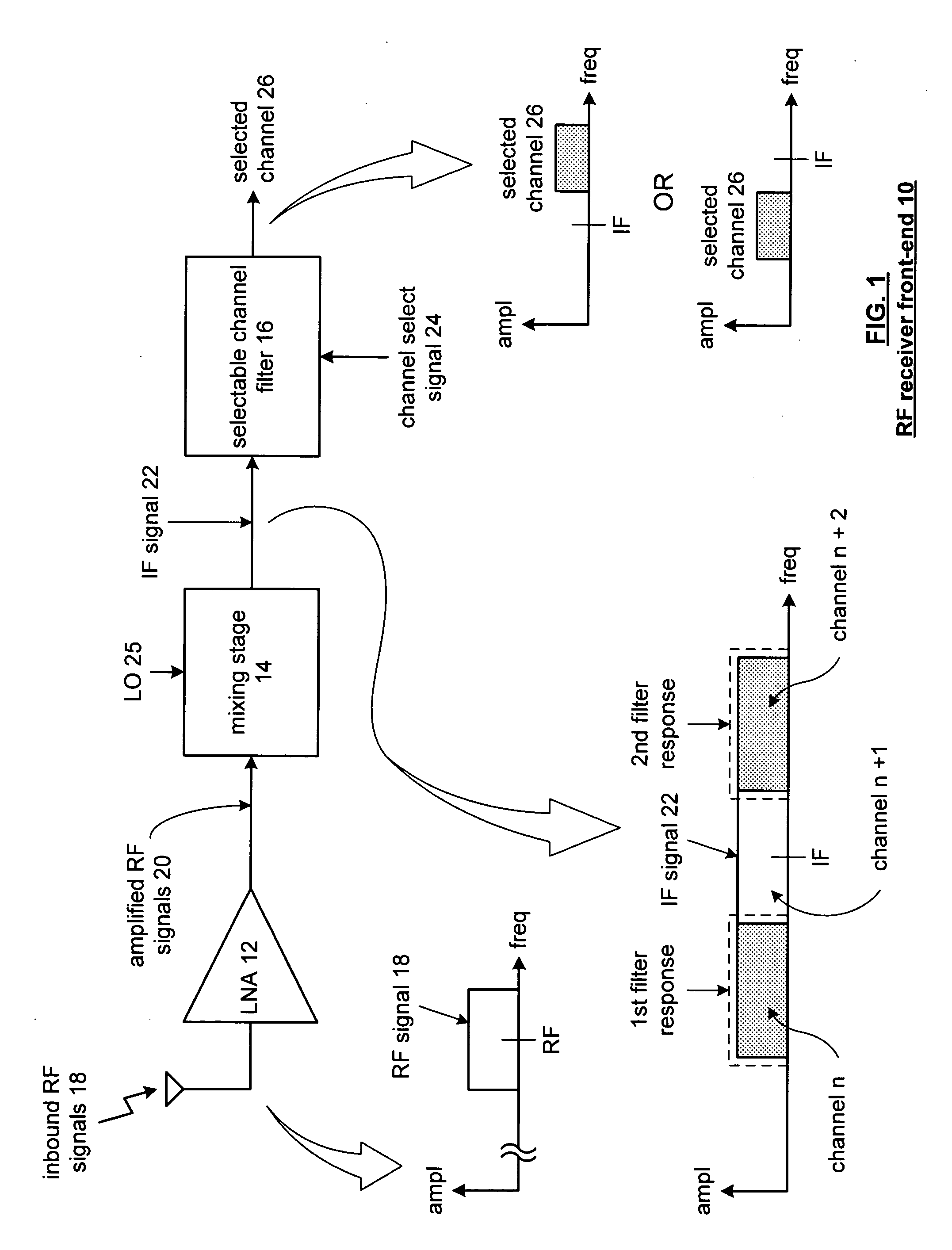
[0017]FIG. 1 is a schematic block diagram of a radio frequency (RF) receiver front-end 10 that includes a low noise amplifier 12, a mixing stage 14 and a selectable channel filter 16. The low noise amplifier 12 is operably coupled to an antenna to receive inbound RF signals 18 and to produce amplified RF signals 20, there from. A graphical representation of the RF signals 18 is shown to include a signal having a certain bandwidth centered at the radio frequency (RF).

[0018] The mixing stage 14 mixes the amplified RF signal 20 with a local oscillation (LO) 25. The local oscillation 25 may be a frequency that is less than the frequency of the RF signals 18 or may be equal to the frequency of the RF signals 18. When the local oscillation 25 is equal to the RF signals 18, the receiver front-end 10 is performing a direct conversion. Conversely, when the local oscillation 25 is less than the frequency of the RF signals 18, the RF receiver front-end 10 is part of a super heterodyne receive...


PUM


Abstract

A radio frequency receiver front-end includes a low noise amplifier, a mixing stage, and a selectable channel filter. The low noise amplifier is operably coupled to amplify inbound RF signals to produce amplified inbound RF signals. The mixing stage is operably coupled to mix amplified inbound RF signals with a 1st local oscillation to produce a 1st intermediate frequency (IF) signal. The selectable channel filter is operably coupled to pass a 1st channel of the 1st IF signal when a channel select signal is in a 1st state and to pass a 2nd channel of the 1st IF signal when the channel select signal is in a 2nd state to produce a selected channel.

Description

BACKGROUND OF THE INVENTION [0001] This invention relates generally to wireless communication systems and more particularly to radio frequency transmitters and receivers used within such systems. DESCRIPTION OF RELATED ART [0002] It is well known that a wireless transmission originates at a transmitter of one wireless communication device and ends at the receiver of another wireless communication device. The structure of the wireless transmission is dependent upon the wireless communication standard, or standards, being supported by the wireless communication devices. For example, IEEE 802.11a defines an orthogonal frequency division multiplexing (OFDM) wireless transmission protocol that included eight 20 MHz spaced channels in the lower band (e.g., 5.15 gigahertz to 5.35 gigahertz) and four 30 MHz spaced channels in the upper band (e.g., 5.725 gigahertz to 5.825 gigahertz). Each channel may include 64 sub-carriers, 48 of which carry data based on a sub-carrier modulation mapping. ...

Claims


Application Information

Patent Timeline
IPC IPC(8): H04B1/00H04B1/16
CPCH04B1/0071
Inventor SUBASIC, BOJANRYBICKI, MATHEW A.
Owner VIXS SYSTEMS INC
Why Eureka
Try Eureka