
Abdominal exercise machine

Inactive Publication Date: 2005-06-23
BOLAND KEVIN O +1
View PDF2 Cites 10 Cited by
  • Summary
  • Abstract
  • Description
  • Claims
  • Application Information

AI Technical Summary

Benefits of technology

[0005] The abdominal exercise machine of the present invention comprises, essentially, a floor supported bench having a mast pivotally connected to one end of the bench by a universal pivot connection. In the preferred embodiment, a full length bench is provided to also support the head of the user. Alternatively, the bench could be half as long and end in the middle of the user's back. A pair of double acting hydraulic cylinders are pivotally connected between the one end of the bench and the mast. The connection of each cylinder to the end of the bench is a universal pivot connection. A foot rest having a heel support is fixed to the upper end portion of the mast and a spring biased bolster is slidably mounted on the mast above the foot rest, whereby the recumbent's instep is engaged by the bolster to hold the feet on the foot rest, and to prevent the feet of the user from sliding out of the foot rest when working the legs / feet.
[0007] The lower end of the mast is connected to the end of the bench by a spring biased detent, to thereby provide multiple settings for varying the resistance of the hydraulic cylinders.
[0008] The mast is configured in an S-shape to position the foot rest closer to the end of the bench which allows the use of a shorter bench, whereby the recumbent utilizes the whole bench with no wasted space.
[0009] A pair of arms are pivotally connected to the sides of the bench, and handles are connected to the free ends of the arms adapted to be grasped by the recumbent. The arms not only make the recumbent feel secure while rotating and twisting the lower body for a complete and effective abdominal workout, but they also stabilize the machine when in use.

Problems solved by technology

While these machines have been satisfactory for their intended purpose, they have been characterized by their limited range of the abdominal muscles being exercised.
For instance, in prior pull / push exercise devices, as disclosed in U.S. Pat. No. 6,500,099 dated Dec. 31, 2002, the recumbent pedals back and forth against the resistance component in one direction, to thereby exercise the abdominals, back and leg muscles; however, this one directional movement does not exercise the recumbent's oblique or side abdominal muscles, and also has a limited effect on the main abdominal muscles.

Method used


Image

  • Abdominal exercise machine
  • Abdominal exercise machine
  • Abdominal exercise machine

Examples


Embodiment Construction

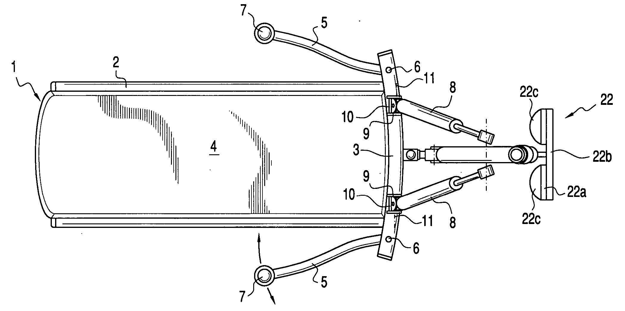
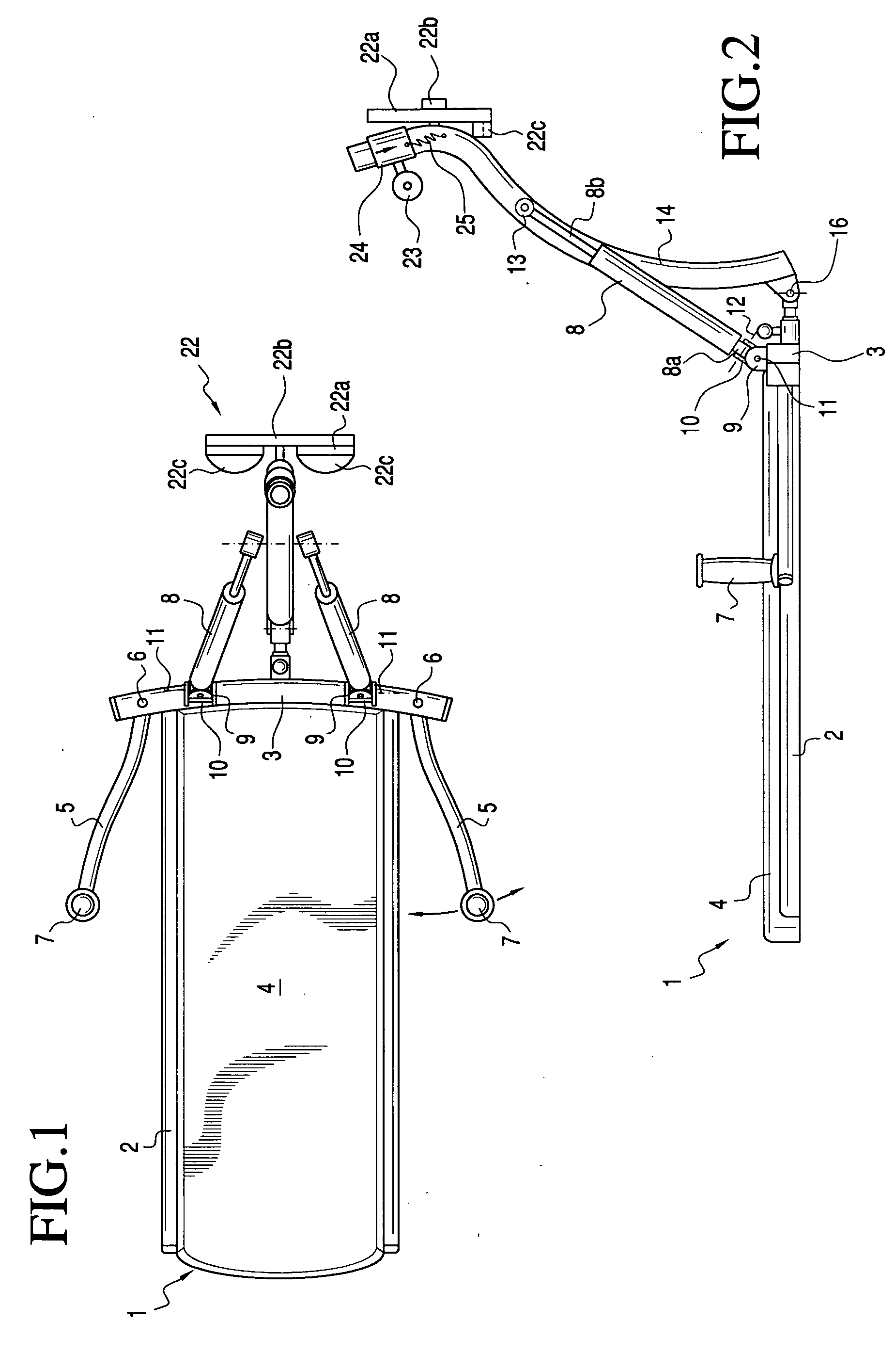
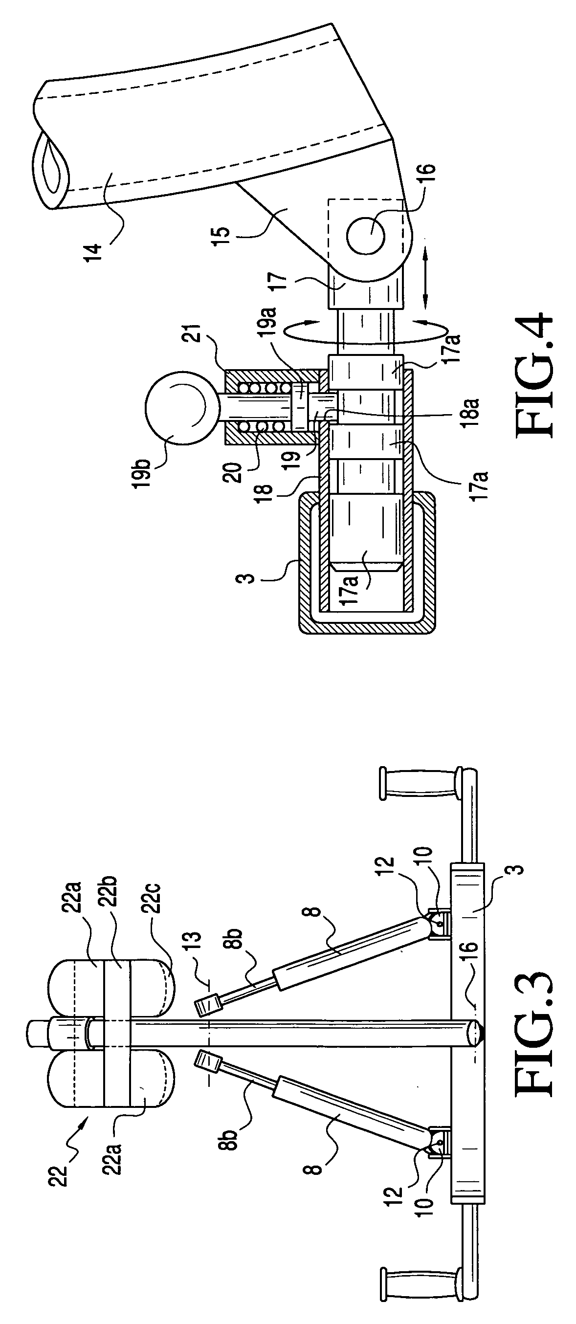
[0014] Referring to the drawings and more particularly to FIGS. 1 and 2, the abdominal exercise machine 1 of the present invention comprises a bench having a pair of longitudinally extending tubular members 2 interconnected at one end by a transversely extending tubular member 3, to thereby provide a frame for supporting a mattress 4.

[0015] A pair of arms 5 are pivotally connected to the outer end portions of the transverse tubular member 3, as at 6, and a handle 7 is connected to the free end of each arm 5.

[0016] A pair of double-acting fluid cylinders 8 are connected at one end to the transverse member 3 by a bracket 9 integral with the transverse member 3. A clevis 10 is pivotally connected to the bracket about a transverse axis, as at 11, and the cylinder end 8a is pivotally connected, as at 12, to the clevis 10, which pivotal connection is normal to the axis of the pivot 11, thereby providing a universal connection between the cylinder end 8a of each double-acting cylinder 8 ...


PUM


Abstract

An abdominal exercise machine having a floor supported bench and a mast pivotally connected to an end of the bench by a universal joint connection. A pair of double acting hydraulic cylinders are pivotally connected between the end of the bench and the mast. The connection of the cylinders to the bench is a universal joint connection. A footrest assembly is connected to the mast. A recumbent exerciser can not only exercise the main and lower abdominal muscles by pushing and pulling the mast against the resistance of the hydraulic cylinders in a back and forth direction aligned with the longitudinal axis of the bench, but also the side or oblique muscles by simultaneously pivoting the mast back and forth in a transverse direction. The machine also allows a combination of the above motions including a circular type motion in either direction, clockwise or counterclockwise.

Description

CROSS-REFERENCE TO RELATED APPLICATION [0001] This application claims the benefit of Provisional Patent Application Ser. No. 60 / 530,252 filed Dec. 18, 2003.BACKGROUND OF THE INVENTION [0002] Various abdominal exercise machines have been proposed including a recumbent leg pull / push exercise device wherein the recumbent, prone on his or her back with the knees bent above the upper body and the feet placed against a resistance component, moves the feet in a pedaling, pull / push movement. [0003] While these machines have been satisfactory for their intended purpose, they have been characterized by their limited range of the abdominal muscles being exercised. For instance, in prior pull / push exercise devices, as disclosed in U.S. Pat. No. 6,500,099 dated Dec. 31, 2002, the recumbent pedals back and forth against the resistance component in one direction, to thereby exercise the abdominals, back and leg muscles; however, this one directional movement does not exercise the recumbent's obliq...

Claims


Application Information

Patent Timeline
IPC IPC(8): A63B21/008A63B21/02A63B23/02A63B26/00A63B71/00
CPCA63B21/0083A63B23/0216Y10S482/907A63B21/1461A63B23/03525A63B2208/0238A63B21/4031
Inventor BOLAND, KEVIN O.MARSCHALKO, CORNELL S.
Owner BOLAND KEVIN O
Learn More