Fluid Dispensation Method

a technology of fluide dispensing and pumping, which is applied in the direction of crankshafts, rotary piston liquid engines, packaged goods, etc., can solve the problems of affecting the efficiency of infusion, and the infusion speed is so small as to reduce productivity, so as to achieve reliable control of infusion operation, no wasted space, and no wasted space

Active Publication Date: 2005-08-25
NIDEC CORP
View PDF3 Cites 0 Cited by
  • Summary
  • Abstract
  • Description
  • Claims
  • Application Information

AI Technical Summary

Benefits of technology

[0012] In an infusion method of the present invention, in order to have the fluid flow out for a predetermined period of time only, a valve mechanism can be utilized. Because the section of the valve mechanism that shuts off the flowpath is adjacent to the basal portion of the cylindrical capillary tube, in the interval from the valve-mechanism shutoff to the capillary-tube tip there is no wasted space. Initiation / cutoff of fluid outflow in the infusion process therefore responds more reliably to on / off switching by the valve mechanism. What is more, because there is no wasted space, along the route reaching from the valve mechanism to the tip end of the capillary tube there is no region in which air bubbles stay. This feature also contributes to reliable control of the infusion operation.
[0013] In an infusion method of the present invention, the infusion work may be implemented applying atmospheric pressure to the fluid. The fact that atmospheric pressure is a pressure source from which relatively steady pressure is inexpensively available enables high-precision fluid infusion jobs to be carried out while equipment costs are held down.
[0014] In an infusion method of the application-subject invention, a valve mechanism that responds with considerable rapidity to the infusion speed may be employed. Doing so makes it all the more possible to reduce infusion-volume discrepancies attendant on infusion initiation / cutoff.
[0015] In an infusion method of the subject invention, lubricating fluid is infused into a dynamic-pressure bearing device. Because the method thus allows a high-precision infusion process to be carried out under a reduced-pressure environment, dispensation of lubricating fluid into a dynamic-pressure bearing device can be efficiently implemented.

Problems solved by technology

When Expression 1 is not satisfied, despite the fluid supply having been stopped, fluid remaining inside the capillary tube continues to flow owing to inertia, which impedes control of the outflow volume.
However, such conditions amount to a situation in which the infusion speed would be so slight as to downgrade productivity.

Method used


Image

  • Fluid Dispensation Method
  • Fluid Dispensation Method
  • Fluid Dispensation Method

Examples


Embodiment Construction

(1) Lubricating-Fluid Infusion Apparatus

[0028] (1-1) Device Overall

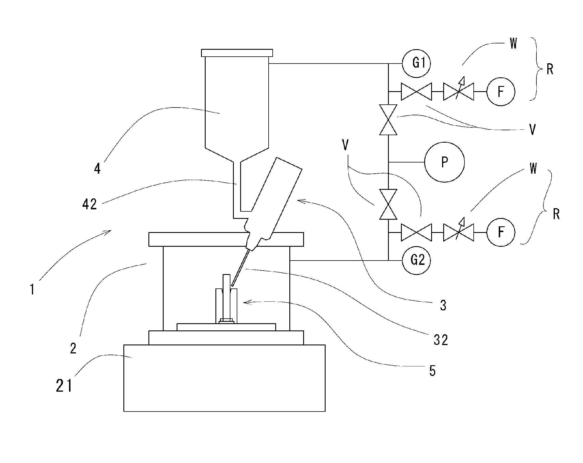
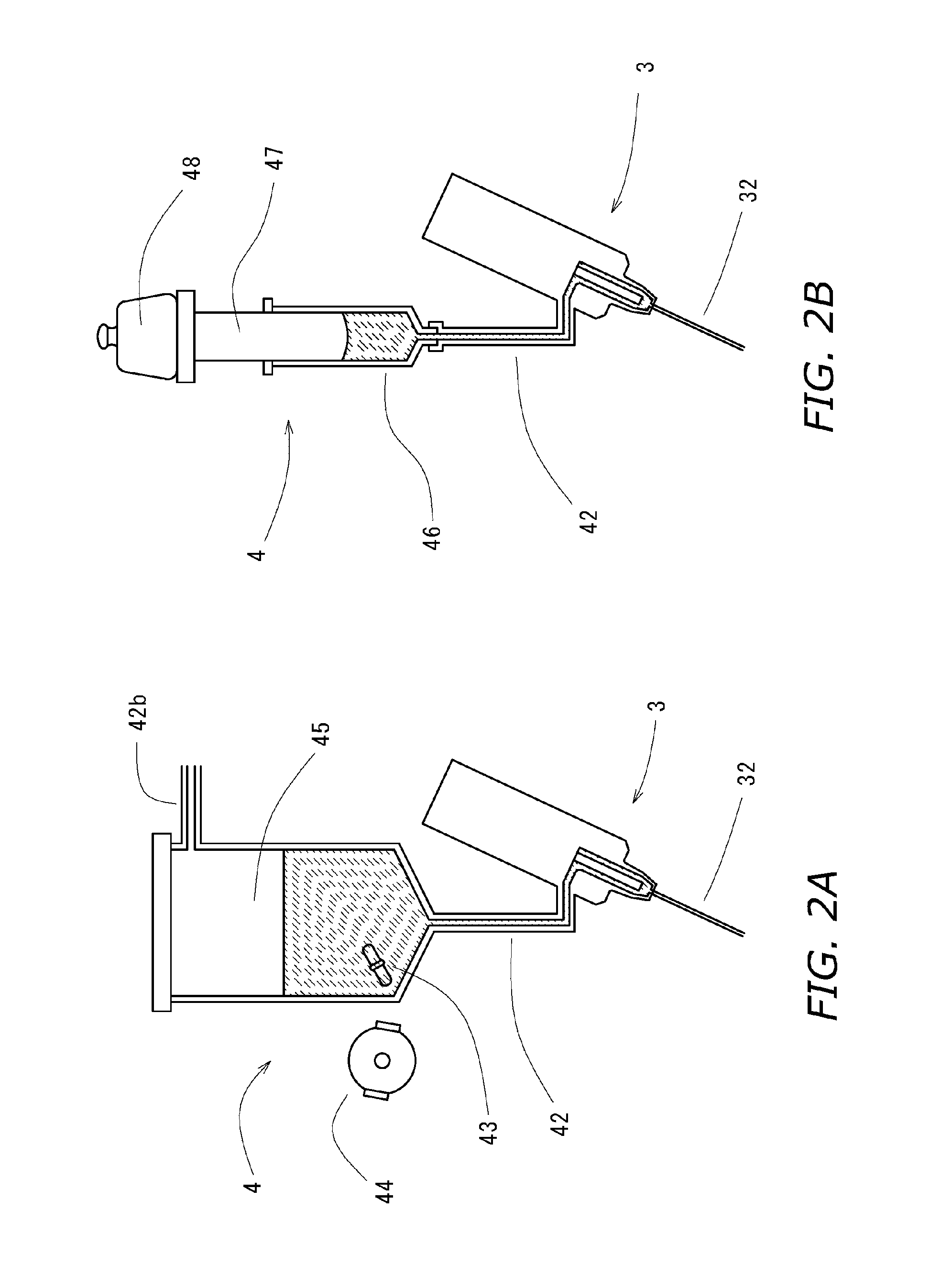
[0029] Reference is made to FIG. 1, which illustrates a lubricating-fluid infusion apparatus 1 for implementing a lubricating-fluid infusion method involving the present invention. The lubricating-fluid infusion apparatus 1 is made up of a vacuum chamber 2, an dispenser 3, a lubricating fluid tank 4, and, for pumping down the interior of these components, a vacuum pumping device and a gas-introduction mechanism R, as well as their connecting supply lines.

[0030] In this implementation, a general rotary pump P is employed as the vacuum pumping device. The gas-introduction mechanism R, comprising a flow control valve W, and a filter F for preventing dust from invading the mechanism, introduces ambient air into the supply lines. To further ensure that invasion of dust is prevented, the flow control valve W adjusted to make it so that the air inflow speed does not grow excessively large. Reference marks G1 and G2 indi...


PUM

PropertyMeasurementUnit
pressureaaaaaaaaaa
pressureaaaaaaaaaa
internal pressureaaaaaaaaaa

Abstract

Under a reduced-pressure environment, stopping at will liquid that flows out from a nozzle tip, or dispensing liquid with the level of energy at which it will not splatter has proven difficult. To address such difficulties, parameters including nozzle bore, and surface tension and viscosity of, and delivery pressure on, a liquid are selected so that the surface tension that acts on the liquid when flowing out from the nozzle tip will be greater than the momentum of the liquid. By dispensing liquid under such conditions, outflow of the liquid is reliably controlled, and rapid infusion work is realized.

Description

BACKGROUND OF THE INVENTION [0001] 1. Technical Field [0002] The present invention relates to fluid dispensation methods whereby a predetermined quantity of a liquid is poured under a low-pressure environment into specific regions of mechanical and other devices. In particular the invention relates to methods of dispensing lubricating fluid into dynamic-pressure bearing devices employed in signal record / playback devices such as hard-disk drives. [0003] 2. Description of the Related Art [0004] In order to carry out dosed infusion of a small volume of fluid into a targeted site, to date microdispensers have been employed. The simplest microdispensers are made up of a small-diameter nozzle, and a mechanism for sending fluids into the nozzle. Components constituting industrially employed microdispensers include a nozzle section, a mechanism that imparts delivery pressure to the fluid, a valve mechanism for controlling fluid outflow, and a mechanism that controls a series of dispenser ac...

Claims


Application Information

Patent Timeline
Patent Type & Authority Applications(United States)
IPC IPC(8): A61M1/00B67B7/00F01C1/02F01C1/063F03C2/00F03C4/00F04C2/00F04C18/00F16C33/14F16N7/14F16N27/00G01F11/00
CPCF16N7/14
Inventor MISU, ISAOUCHIYAMA, MASAAKIYOSHIDA, TATSUYAICHINOSE, TAKESHI
Owner NIDEC CORP
Why Eureka
Try Eureka