
Rapid depolyment portable interactive kiosk

a kiosk and interactive technology, applied in the field of portable kiosks, can solve the problems of inability to intuitively use or setup difficulty in accessing the emergency site, and the manpower required to deliver, setup and operate these types of mobile response units, etc., and achieve the effect of not requiring much skill or time, easy folding and easy folding

Inactive Publication Date: 2005-06-23
LAFLEUR BERNARD B
View PDF9 Cites 101 Cited by
  • Summary
  • Abstract
  • Description
  • Claims
  • Application Information

AI Technical Summary

Benefits of technology

"The present invention provides an improved interoperable communications device that solves the problems of being unable to communicate with other devices easily and the need for a portable kiosk that can be easily folded and transported. The device has telecommunications functions, data input and output functions, and computer functions, including a battery power supply, electronics for recharging, a computer with hard disk drives, a LCD display, a keyboard, a scanner, GPS, a cellular and satellite communications module, a printer, a computer with integrated functions, a display, and a portable kiosk that can be easily folded and stored away. The device is designed to be easily deployed and accessed by incident commanders, first responders, and other agencies and commercial organizations. The device is designed to be used in emergency events and is designed to survive handling mishaps and to keep the internal electronic components safe and functional. The device is designed to be portable and easily folded for easy storage and transportation. The device is designed to provide a unified interoperable communications delivery platform designed to meet the mission critical requirements of homeland security."

Problems solved by technology

The problem with these solutions is multifaceted, beginning with the technology being housed in a wheeled or track vehicle.
Debris, infrastructure failure (bridges), inaccessible roadways, and evacuation routes used by pedestrians make access to the emergency site difficult if not impossible.
Another major issue is the manpower required to deliver, setup and operate these types of mobile response units.
Many of the subsystems are not intuitive in use or setup, and must be operated by highly trained and skilled individuals.
Deploying these types of mobile response units takes a lot of time, manpower, energy and resources.
Usage of the mobile response units by front line first responders or on-scene incident commanders are rarely if ever available.
Mobile response units are also highly vulnerable to drive train failure.
This failure could manifest itself in the form of a flat tire, engine failure, overheating, broken or damaged axles and a host of other mechanical problems or failures.
The cost of mobile response units is very expensive running as high as several hundred thousands of dollars for a single unit.
The high cost of these units is a barrier to the mission goal for acquisition and usage of interoperable communications for national, state, local, and commercial organizations to strengthen homeland security.
Current transportable systems have many shortcomings and fail to adequately provide a comprehensive solution to the problem.
Some of the problems include the inability to operate in varied environmental conditions ranging from daylight readability through extreme climate conditions.
Many of the subsystems are not intuitive to use or setup and must be operated by highly trained and skilled individuals.
General public usage is not viable due to the configuration and layout of these current transportable systems.
This inherent design limitation fails to address the entire life cycle requirement of an event, which includes usage by the general public for relief aid processing and community restoration.
The man-machine interface is not well thought out.
Ease of use or access by individuals with a disability or operation while wearing a decontamination suit or winter clothing has not been adequately addressed or access provided.
The current systems have not yet supplied the emergency response community with the technology that it needs for this mission.
For example, the kiosk in U.S. Pat. No. 6,289,326 to the Applicant does not fold away into a small case, and does not have the telecommunications technology needed for on the field monitoring.

Method used


Image

  • Rapid depolyment portable interactive kiosk
  • Rapid depolyment portable interactive kiosk
  • Rapid depolyment portable interactive kiosk

Examples


Embodiment Construction

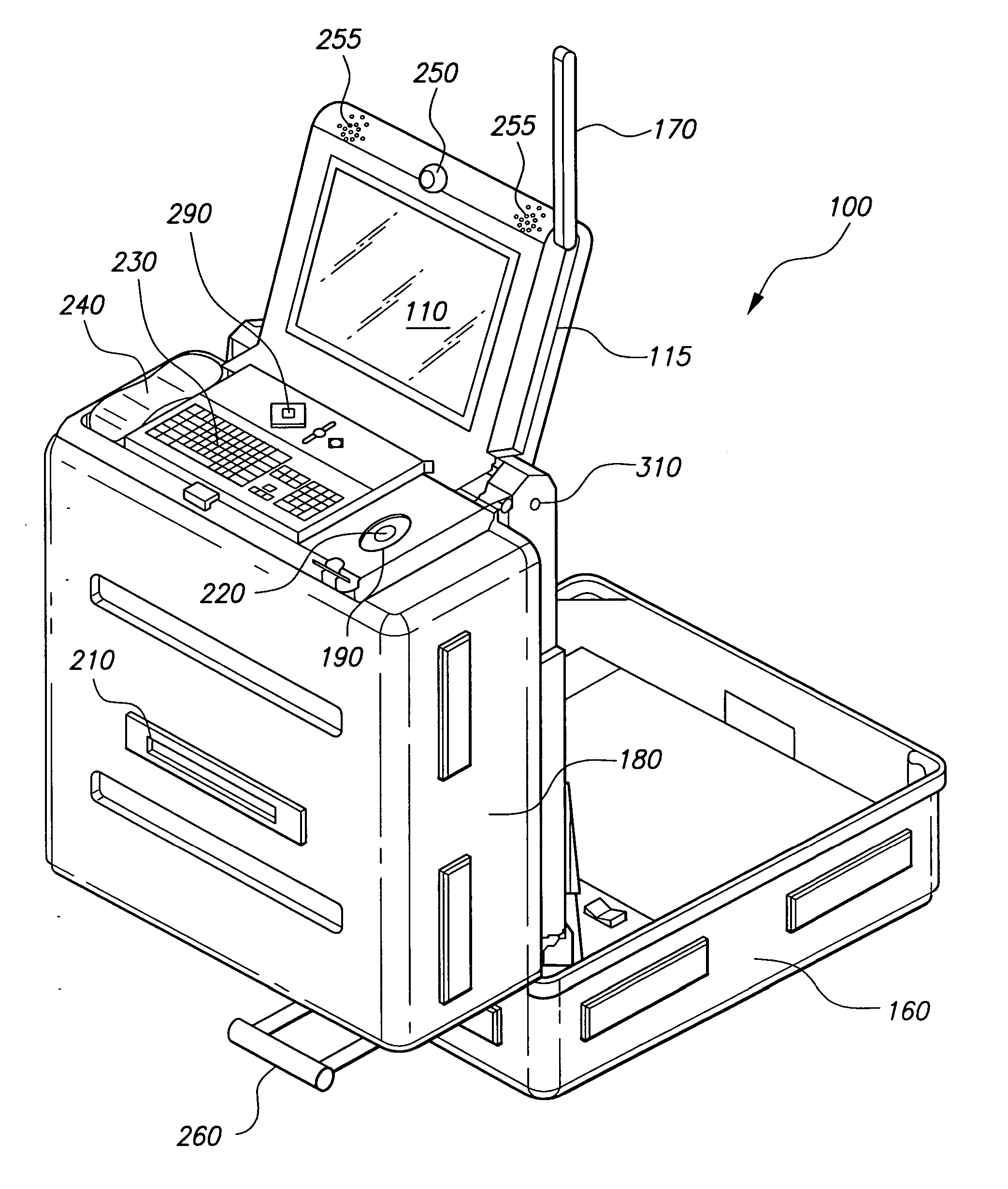
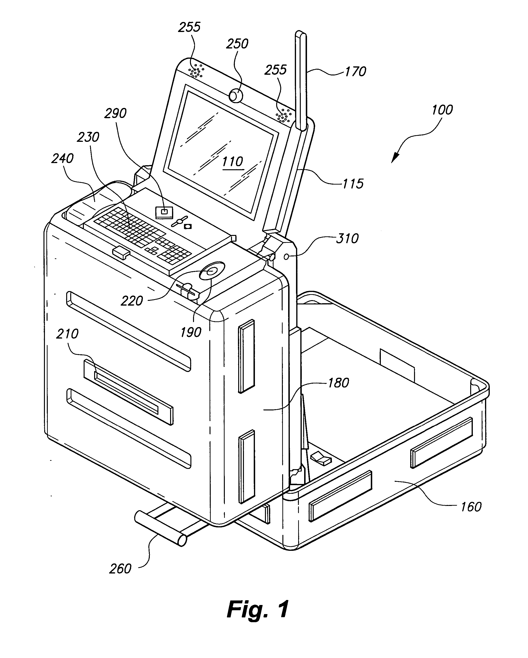
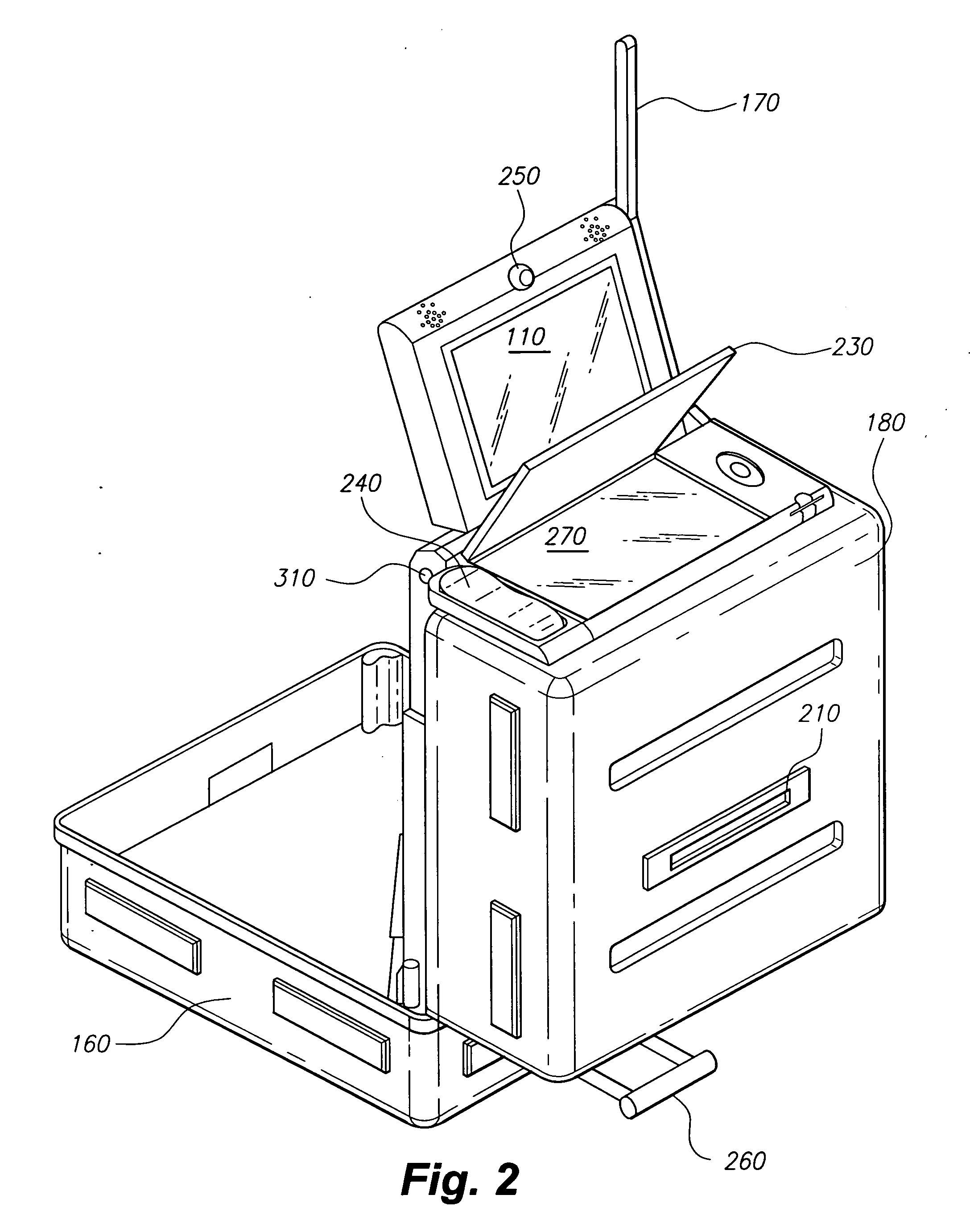
[0037] Turning to the figures, FIG. 1 illustrates the Rapid Deployment Portable Interactive Kiosk (RPPiK) 100 according to the principles of the present invention. The kiosk 100 in FIG. 1 is in a fully deployed position. As illustrated in FIG. 1, keyboard 230 is disposed 35 inches off the ground. Keyboard 230 is preferably a spill proof keyboard. Behind keyboard 230 is an EZ Access™ section 508 ADA compliant interface 290 enabling persons with limited hand use and / or limited or no vision to use the kiosk. To the left of keyboard 230 is a telephone handset 240. Telephone handset 240 has a volume control and has a jack for a headset. The telephone handset 240 along with the other features of the kiosk can enable the user to command and control teams of people in an emergency. To the right of keyboard 230 is biometric ID 220. Biometric ID 220 is a fingerprint scanner that is used to either grant or deny access of certain persons to the kiosk. The biometric ID 220 can provide usage auth...


PUM


Abstract

A portable information kiosk. The kiosk has a self contained power supply for a computer, a display, a digital camera, a cellular, satellite capable telephone, an antenna, a printer and a flat bed scanner, all electrically connected to each other and capable of being stored in a small carrying case. A method of deploying the kiosk does not require any attaching of parts together and can be done quickly. The kiosk is ideal for in the field communications and data acquisition, such as in disasters, emergencies, or any in the field environmental monitoring.

Description

CROSS-REFERENCE TO RELATED APPLICATION [0001] This application claims the benefit of U.S. Provisional Patent Application Ser. No. 60 / 503,483, filed Sep. 17, 2003.BACKGROUND OF THE INVENTION [0002] 1. Field of the Invention [0003] This invention relates to a portable kiosk having a computer and telecommunications capabilities, and that can be used in the field in an emergency or other remote activity. [0004] 2. Background of the Invention [0005] Various components and systems currently exist in the marketplace attempting to address the requirements of “Interoperable Communications.” The systems that have the largest range of functional technology are housed within large wheeled or track vehicles. Others are housed within mobile trailer configurations that must be towed to the site. Some of these types of mobile solutions incorporate a vast array of technology enabling “Interoperable Communications” from the physical location of the unit once it is deployed and operational. [0006] The...

Claims


Application Information

Patent Timeline
Patent Type & Authority Applications(United States)
IPC IPC(8): G07G1/00
CPCG07G1/0018G06Q30/0601
Inventor LAFLEUR, BERNARD B.
Owner LAFLEUR BERNARD B
Learn More