Method and apparatus for determining a spanning tree

Active Publication Date: 2005-06-23
EXTREME NETWORKS INC
View PDF6 Cites 38 Cited by
  • Summary
  • Abstract
  • Description
  • Claims
  • Application Information

AI Technical Summary

Benefits of technology

[0024] According to one aspect of the invention, it is realized that use of spanning tree protocol in particular portions of a network may not necessarily be desired. For instance, in reliable networks where service levels are guaranteed, in network topologies that have a particular amount of redundancy or in network topologies that inherently or otherwise prohibit looping, the execution of spanning tree may not be necessary. For instance, in an MPLS network, the core network may be a reliable network in which executing an STP is not necessary. An MPLS core may be made more reliable, for example, using techniques such as fast-reroute of label-switched paths (LSPs), redundant LSPs, automatic protection switching (APS), or other te

Problems solved by technology

Also, in network types such as circuit-switched networks or other types of networks where loops are not a concern, an STP does not provide much advantage.
Indeed, in a large network, execution of a spanning tree protocol may become unstable.
In this model, there is a scalability problem f

Method used


Image

  • Method and apparatus for determining a spanning tree
  • Method and apparatus for determining a spanning tree
  • Method and apparatus for determining a spanning tree

Examples


Embodiment Construction

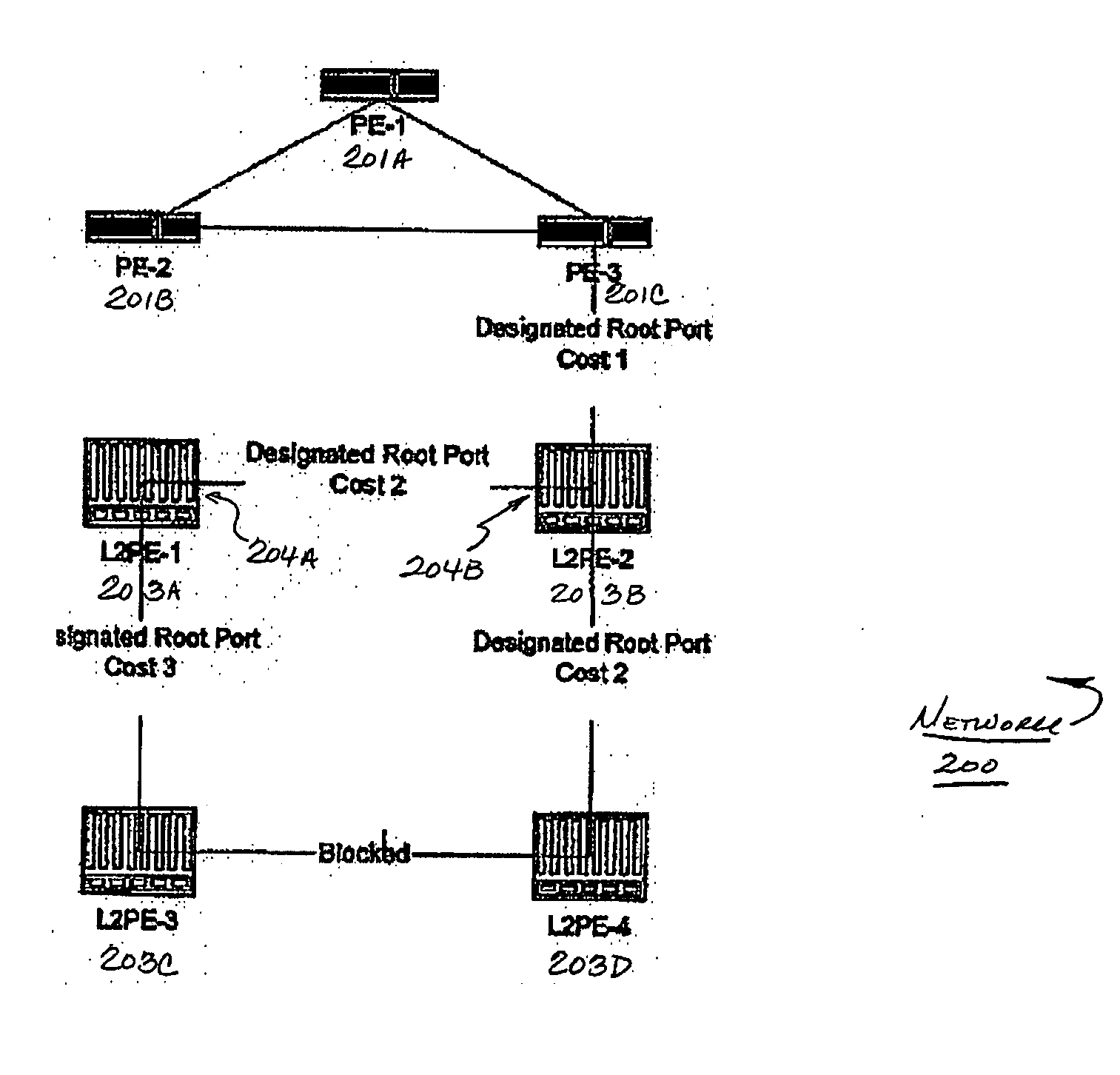
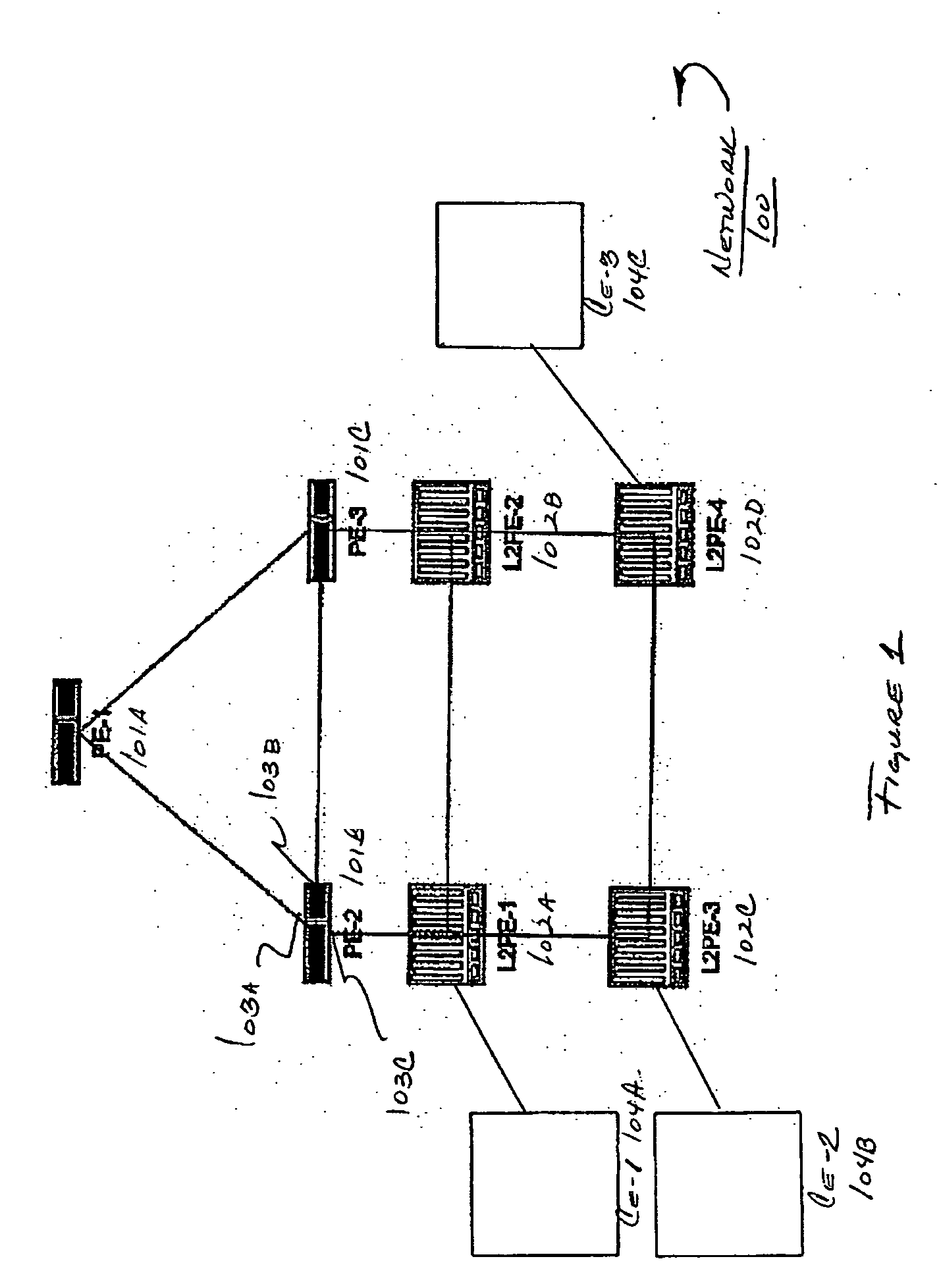
[0044]FIG. 1 shows a block diagram of a network in which various aspects of the present invention may be practiced. A network 100 includes a number of network forwarding nodes or systems 101A-101C and 102A-102D for communicating data between hosts (not shown) that are coupled to network 100 through one or more network forwarding nodes (e.g. nodes 102A-102D).

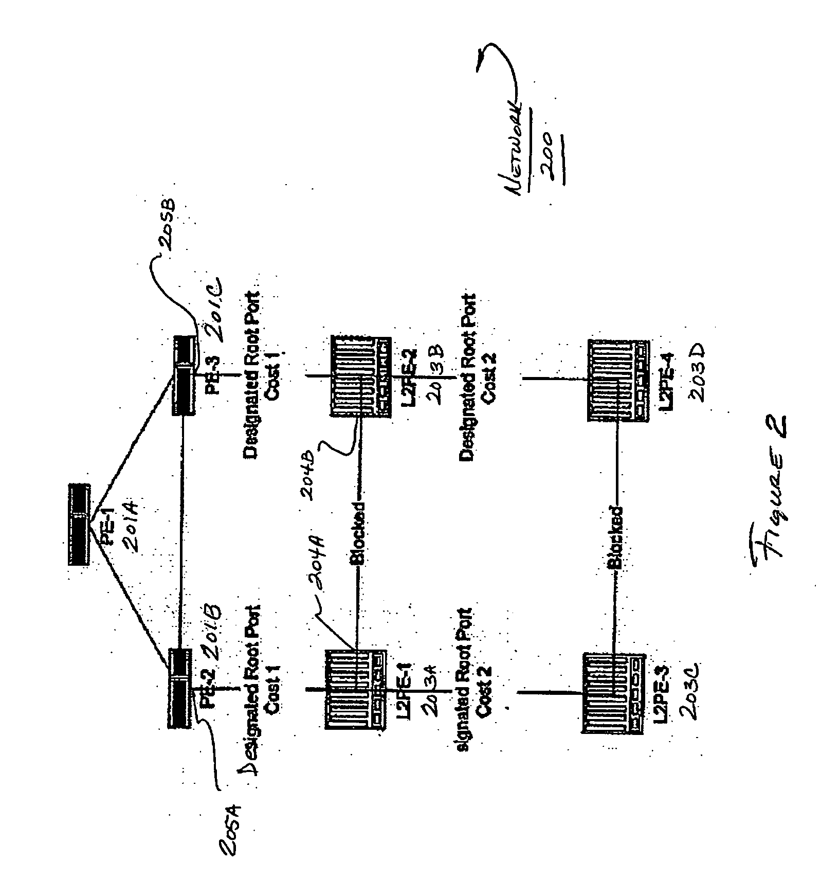
[0045] According to one embodiment of the invention, a spanning tree protocol may be adapted to work more optimally in particular network topologies.

[0046] In the topology shown in FIG. 1, there are a number of provider edge (PE) devices that communicate over a core network connecting the nodes. For example, as shown in network 100, a provider edge system PE-1 (Item 101A) is coupled to provider edge devices PE-2 (Item 101B) and PE-3 (Item 101C). For example, PE devices may be coupled by a network implementing Multiprotocol Label Switching (MPLS) that transmits Layer 2 MAC frames between networks.

[0047] One or more Layer 2 prov...


PUM


Abstract

It is realized that the use of a spanning tree protocol in particular portions of a network may not necessarily be desired due to performance and stability reasons. A method and system is provided for executing a revised spanning tree algorithm that performs more optimally in particular network topologies. In one aspect, a spanning tree protocol is executed over a first and second network connected by a third network, wherein the spanning tree network is disabled in the third network. The third network may be, for example, a core network through which first and second Layer 2 networks are bridged. The first and second networks may be coupled by another network or network connection, and it may be preferable to allow the operation of the spanning tree network between the first and second coupled networks for the purpose of fail over to redundant paths. In network forwarding devices positioned at edges of the core network, the operation of the STP over interfaces where network tunnels of each network forwarding device attached to the core network may be inhibitied (e.g., turned off). A phantom root bridge may be created that does not correspond to an actual network forwarding node, and this phantom root bridge may have a bridge identifier which is used by network forwarding nodes as the root bridge. In this manner, STP protocols may work as intended in peripheral networks, while STP does not need to be executed in the core.

Description

RELATED APPLICATIONS [0001] This application claims priority under 35 U.S.C. § 119(e) to U.S. Provisional Application Ser. No. 60 / 435,492, entitled “PHANTOM ROOT SPANNING TREE ACROSS A FULL MESH CORE,” filed on Dec. 20, 2002, which is herein incorporated by reference in its entirety.BACKGROUND OF THE INVENTION [0002] 1. Field of Invention [0003] The field of the invention relates generally to network communication, and more specifically, to networks using a spanning tree algorithm to determine network topology. [0004] 2. Discussion of Related Art [0005] Communication networks are generally used to transfer information between computers, referred to in the art as hosts. These hosts may be, for example, general purpose computer systems (e.g., personal computers (PCs), servers, etc.) that communicate data. Generally, a network includes one or more components referred to herein as network forwarding devices that are adapted to receive and forward messages from / to hosts. These network fo...

Claims


Application Information

Patent Timeline
IPC IPC(8): H04L12/56
CPCH04L45/02H04L45/50H04L45/48H04L45/04
Inventor TSILLAS, DEMETRIOS JAMES
Owner EXTREME NETWORKS INC
Why Eureka
Try Eureka